Current Design and Construction Practices for Micropile Supported Foundations of Electrical Transmission Structures in North America
Nickolas G. Salisbury, President, Crux Subsurface Inc., Spokane, Washington USA
Steven A. Davidow, P.E., S.E., Vice President, Crux Subsurface Inc., Spokane, Washington USA
This paper will discuss innovative micropile foundation designs utilizing advanced steel and concrete caps constructed on several recent transmission projects. It will detail the foundation design selection process, 3D finite element simulation and design, steel cap testing procedures, construction challenges encountered, and specific benefits that foundation design provided to the projects. Many of the construction sites detailed in the paper were located in remote, rugged terrain and required helicopter-only construction methods. At these sites, a design-build micropile foundation system was proposed and ultimately employed as an alternative to traditional concrete drilled shaft foundations. Typical micropile foundation construction included a circular array of battered micropiles installed to depths of approximately 35 feet at each tower leg or pole base. A concrete or steel pile cap was then selected to transfer the load from the stub angle to the micropile array. Concrete caps were analyzed using Strut and Tie modeling in combination with 3D rendering of piles, reinforcing steel, and concrete to optimize constructability. Advanced structural analysis was utilized in the design phase of the steel caps, involving finite element modeling to pinpoint areas of potential weakness and develop detailed fabrication drawings. A variety of pile-to-cap connection types were considered to quantify the effect of varying degrees of pile head fixity on structural performance. These advancements in micropile foundation design and construction have been instrumental in the success of several large scale transmission projects.

Stress Predictions From Finite Element Modeling
Introduction
With an aging electrical infrastructure and steadily increasing power demands in North America, there continues to be strong investment, both publically and privately, in the electrical transmission and distribution sectors. Although there has been a considerable effort in development and implementation of high efficiency products consuming electricity over the past twenty years, electrical demand has grown nearly 35%. This trend is expected to continue, due in large part to population growth and the increasing power demands created by the development of the internet infrastructure and data transfer demands.
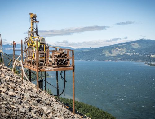
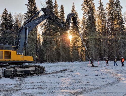
Developing energy production from remote renewable resources within North America and transmitting the produced power to metropolitan areas requires transmission alignments to cross rugged terrain and environmentally sensitive areas. Helicopter assisted micropile foundation construction has been instrumental in solving both access and environmental constraints challenging the development of critical power infrastructure.
Based upon structure loading demands, site topography, and limited area of impact constraints, complex geometric pile caps are often desired to simplify pile installation and transportability of the cap to the construction site. Steel and concrete pile caps have been designed with classical methods and Finite Element Analysis to drive innovation and economy into these foundation structures.
This paper discusses the impact of micropile construction and related design techniques on the success of power transmission development. Several recently completed major transmission projects which were challenged with access and environmental restrictions will serve as case studies for this technical presentation. Design techniques will be outlined and discussed as well.
Site Constraints Require Innovative Approaches
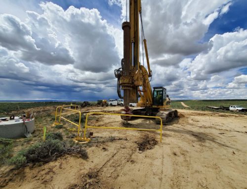
Overhead transmission structures founded on stable soils with conventional access are traditionally constructed on drilled shaft foundations. Sites located in difficult-to-access or environmentally sensitive areas, where road construction is either not feasible or not permitted, requires the implementation of alternative foundations that can be constructed through helicopter support. Specialized equipment and materials utilized for micropile foundation construction are conducive to efficient helicopter transport, as they can be more compact and lightweight than drilled shaft equipment. Micropiles can also accommodate a wide range of geotechnical conditions, rendering them an ideal alternative for transmission projects which may include foundation sites in desert, mountain and marine environments along a single alignment.
Crux recently completed design and construction on two large scale lattice tower projects which required helicopter supported micropile foundations due to limited access constraints. The Sunrise Powerlink project completed for San Diego Gas and Electric (SDG&E) was composed of a 117-mile long 500 kilovolt (kV) transmission line extending from the desert region near El Centro, California through National Forest Service land and mountainous regions into San Diego, California. The Northwest Transmission Line (NTL) project in British Columbia (BC), Canada for BC Hydro was composed of a 213-mile long 287 kV transmission line extending through remote, mountainous terrain between Terrace, BC and Bob Quinn Lake, BC. Crux utilized a fleet of specialized construction drill rigs that can be track-mounted or placed on specialized drill platforms to access logistically challenging project locations. Lightweight and componentized, the drills can be broken down into 4000-pound components and easily moved by medium-lift helicopter. These hydraulic rotary drills are capable of handling up to 9-inch diameter casing material. To assist with tighter schedule demands, steel pile caps were designed as an alternative to the cast-in-place concrete caps previously implemented at lattice tower micropile foundation sites. Steel pile caps require less onsite construction time and provided the contractor with more flexibility and control over the critical path of construction activities.
Variable Subsurface Conditions Present Additional Challenges
With long alignments passing through remote or sensitive terrain, it is not uncommon to begin design with little or no geotechnical information at the proposed micropile construction sites. Preliminary designs are developed based upon any geotechnical data gathered in the vicinity of the project, supplemented with a review of pertinent geologic mapping of the project area and site reconnaissance.
While construction methods between the Sunrise and NTL projects were similar, the geotechnical and environmental conditions were vastly different. The Sunrise project traverses varied terrain and diverse geologic conditions. The geologic units encountered along the alignment consist of metamorphic rocks, granitic rocks, and Tertiary and Quaternary sedimentary rocks, with localized volcanic rocks. The sedimentary rocks consist of nonmarine (some marine in Imperial Valley) fluvial, lacustrine, and volcaniclastic strata. The sedimentary strata unconformably overlie the metamorphic and batholithic rocks, and are basin-fill deposits in Imperial Valley. The NTL project traversed highly variable terrain comprised of variable thicknesses of colluvium, fluvial sands and sand/gravel mixtures, overlying glacial till and/or bedrock. The bedrock geology consisted predominately of medium to fine-grained sandstone, siltstone, and shale with small areas of volcanic rock outcropping.
With a range of probable geotechnical overburden and bond units defined, micropile design solutions for all possible combinations of overburden and bond unit materials can be derived, considering variable site topography in the analysis. Depending upon the variability of soil and rock materials anticipated on a project in combination with variable site topography, the number of geotechnical design conditions requiring solutions can be immense.
One of the unique aspects of micropile construction is the opportunity to characterize the soil conditions at a site during the installation process. This characterization process allows the contractor to calibrate the specific site conditions for a given structure to a predetermined design, allowing for real-time optimization of the foundation. For example, if a construction site is composed of a ten-foot thick layer of medium dense soil overlying bedrock, it would be highly conservative to install a design solution which assumed all soil for both lateral and axial support of the pile loading.
If the contractor can characterize the geotechnical conditions in the overburden material for lateral resistance at various depths and continue characterization into the bond unit, the installation of the piles can be site specifically optimized in terms of both the quantity of piles installed and the lengths of cased and un-cased sections of the piles. This process of real-time optimization is critical to reducing project cost and schedule related to micropile installation, and forms the basis for implementing the design-build construction methodology to mitigate the risk implicit in transmission and distribution foundation construction. This process was also significant in ensuring micropiles would be a competitive solution with other traditional and alternative foundations utilized in the electric power industry.
Due to the nature of loading applied by typical electrical structures, overturning moment derived into cyclical tension and compression in combination with shear, composite micropiles are generally employed on all projects. Composite micropiles are composed of steel casing filled with grout and a high-strength central piece of threaded reinforcing steel. The cased section is installed in the upper overburden unit and provides lateral resistance, while the reinforcing bar and grout are extended into the lower bond unit and provide axial resistance. With the wide variety of anticipated geotechnical conditions, ranging from near surface rock to thick layers of colluvium, the design and construction focused on two types of micropiles for structural support of pile caps.
Composite micropiles bonded in both rock (Type A) and soil (Type B) were utilized on both projects. The casing size ranged from 5.5-inch 50 ksi material to 8.625-inch grade 80 ksi material. The internal reinforcing steel was composed of a single threaded rod, ranging from 1.75-inch diameter 75 ksi material to 2.5-inch diameter 127 ksi material. All piles were installed in a battered circular array, with pile batter angles ranging from 2.5 degrees to 12 degrees.
Steel Pile Caps Supported by Micropiles Solve Challenges of Difficult Terrain
Steel pile caps were proposed for both projects in an effort to accelerate foundation construction schedule. The steel caps were designed to fasten to the micropiles without field welding; hot work was not permitted on a large portion of the Sunrise project alignment. The bolted connections between the micropile and the cap would need to accommodate minor deviations from intended pile locations, and provide enough fixity to limit overall foundation movements to prescribed limits of the electrical structures. Foundation loads were determined by the tower’s ultimate capacity. Load factors were prescribed by the design specification for both the cap and pile designs. The design life is typically defined as 75 years for structures of this type. Due to the rigorous environment these systems would be employed in, it was assumed that the caps would need to perform without regular scheduled maintenance.
The caps for both Sunrise and NTL were designed using finite element modeling to estimate peak stresses and deflections. In the process of optimizing the steel pile caps for weight and transportability, the final design focused on a series of stiffening and bearing plates welded together in a radial formation. Finite element models can generate a tremendous amount of critical performance data for structures with complex geometry. It is in the interpretation of these results that structural optimization evolves. Critical features of the model and analysis include proper modeling of constraints and fixity, application of loads (point versus area), and support stiffness (fixed versus spring). Von Mises stress criterion was utilized to predict the onset of yielding within the steel cap plates and an eigenvalue analysis was utilized to review stability of unstiffened edges of the plates and allow for iterative redesign. Individual plate principal stresses were utilized to develop force requirements for connections and determine/economize weld sizes.
Sunrise was the first lattice tower project for which steel micropile caps were comprehensively tested and ultimately installed. Two prototype pile caps were constructed and installed on micropile foundations at a test site near the project alignment. A full scale load test was conducted, applying 1000 kips of compression load and 300 kips of lateral load simultaneously. Deflections in the micropiles and pile caps were measured during the load test and compared with Finite Element Analysis to confirm the model’s predictions. As shown in Figure 7, the measured foundation deflection under lateral load closely followed the finite element predicted movement. The execution and success of the full scale load test marked the preliminary acceptance of the steel pile cap design.
Numerous methods of corrosion protection were contemplated by the project team. The chosen method would need to provide resistance in the case of partial burial for short periods of time, as a majority of micropile foundations were located on steep slopes. Difficulty of access to remote sites also necessitated a corrosion protection method that could withstand adversity between longer inspection intervals. The Subcontractor and Owner contemplated several methods, eventually narrowing the options to self-weathering steel (ASTM A588) and Hot Dip Galvanizing (HDG).
Although both methods were found to satisfy the corrosion protection requirements, the owner chose to specify HDG as the preferred corrosion protection methodology. Hot dip galvanizing of the complex weldment proved to be challenging. Thermal stresses caused by the HDG process exceeded stress that would be induced during the normal performance of the pile cap. The Subcontractor and their steel fabricators and galvanizers tested a multitude of variations in fabrication and dipping to arrive at a thorough and repetitive process for dipping without manifesting stress indications. An inspection process was employed on the galvanized caps to identify heat induced indications. Ultimately, the design team developed a set of fabrication specifications that relied heavily on AWS D1.1 for the majority of the pile cap and D1.5 for the attachment of the tower’s stub angle to the top plate of the pile cap. A short list of fabricators was selected, prequalified, and audited for QA/QC procedures at their facilities by the Owner.
Concrete Pile Caps Supported by Micropiles Provide Higher Load Carrying Capacity
The benefits of utilizing steel caps lie in the ability to prefabricate the cap and place it in a single set. As structure loading increases, the amount of steel and subsequent weight of the cap become problematic, particularly when dealing with helicopter assisted construction in remote access areas. In these instances, a conventionally reinforced concrete cap becomes most effective in transmitting the structure reaction to the micropiles. Relatively small concrete pile caps supported by micropiles have been utilized to resist overturning moments of 50,000 ft-kips imposed by large dead-end tubular steel poles. With larger overturning moment loads, it is most economical to push the micropiles further apart, reducing the axial demand generated by the resulting force (reaction) couple. This places more flexural demand into the pile cap, which can make resulting steel cap designs uneconomical compared to concrete pile cap solutions.
Concrete pile caps are generally controlled by some mechanism of shear failure rather than flexural demands. This is particularly true with electrical structure micropile installations, where the micropiles are placed as close together as the design will allow, minimizing the impacts on the surrounding site and topography. While there are many advanced analysis methods for thin slabs, such as those used in elevated floors, there are few options for analyzing thicker concrete structures like pile caps. The predominant method of analysis and design for concrete pile caps today is founded upon empirical or semi-empirical models, based on one-way or punching shear failure, which generally leads to densely reinforced structures.
Often times the concrete cap thickness will be dictated by a prescribed structure base elevation, which is equal to the top of concrete cap. Maintaining this top of concrete elevation on sloping ground with a tight micropile array will result in a small width to thickness ratio for the reinforced concrete element. This ratio is an indicator of the transition between flexural and shear behavior of the concrete element.
Two analysis methods, Strut-and-Tie Modeling and Finite Element Analysis, have been employed with concrete cap designs to more accurately predict the distribution of internal forces and economically distribute reinforcing to resist these forces. Both methods provide a sophisticated means of approximating the flow of force from the point of application (pole or tower) to the point of support (micropiles) and result in a more reasonable reinforcing solution.
Strut-and-Tie Modeling looks at a deep concrete flexural element and discretizes the component into compression struts and tension ties, based upon an assumed “truss” model. The method was developed primarily to analyze structures in a single plane, so some adaptation is required to employ it in three dimensions for pile cap design. Once an initial “truss” model has been developed, the nodal geometry of the truss can be iteratively refined to arrive at the optimal final solution. A design criterion must also be developed to address the unreinforced section of the structure in instances where the reinforcing scheme may not extend into these regions.
Finite Element Analysis, as described in the steel cap section, allows for a more detailed prediction of internal stress and deflection, based upon distortional energy theory. While steel elements can be readily analyzed with little modification to the finite element program, care must be taken when analyzing concrete elements as their behavior will change under various loading conditions. Steel elements are generally analyzed utilizing shell elements to more accurately predict behavior as a linearly elastic material. Concrete is generally modeled as a solid element, with modifications made to represent behavior of the material as it changes from uncracked to a cracked section as the material passes through its rupture strength.
Concluding Observations
Micropiles provide a unique solution to developing high capacity foundations for areas with limited access. Utilizing lightweight and helicopter transportable equipment allows for installation that generates a minimal area of impact. The ability to characterize actual site specific geotechnical conditions during the installation of the micropiles, in combination with a strong design-build relationship between contractor and engineer, allows for real-time field optimization to occur.
Installation of prefabricated steel pile caps has generated a significant advantage to schedule and safety on these challenging construction sites. The implementation of lightweight steel caps has been precipitated through the use of advanced Finite Element Analysis techniques. Utilizing these techniques to validate plate buckling and yielding, and to determine welding requirements based upon principal plate stresses, allows for a significant reduction in total pile cap weight.
Utilizing similar advanced techniques for concrete analysis has created vastly more economical concrete pile cap designs. By pushing installed micropiles further apart and utilizing concrete caps to support structures over the longer spans between piles, substantial overturning moments can be resisted. By making use of concrete cap thickness dictated by site and structure geometry, economical reinforcing layouts can be employed, allowing for rapid construction and more field tolerance.
The electrical transmission and distribution industry is rapidly expanding; with investment in high-voltage electrical transmission expected to exceed $41 billion in the United States between 2011 and 2020. Current resources have become exhausted and increasing demand for power has led to investment in infrastructure upgrades as well as new line construction. Consumers and state mandates are calling for an increased portion of this power to come from renewables, which are often located in remote regions. The task of transporting these renewables to metropolitan areas, frequently crossing rugged and environmentally protected terrain, has introduced a number of foundation construction challenges to project owners.
Through an increase in site constraints, continual advances in technology and performance history generated by a large number of installations, the use of micropile foundations will be employed in a wider range of applications as compared to conventional methods.
Nickolas G. Salisbury, President, Crux Subsurface Inc., Spokane, Washington USA
Steven A. Davidow, P.E., S.E., Vice President, Crux Subsurface Inc., Spokane, Washington USA