Designing for Lateral Spread in Deep, Liquefiable Soils
Accommodating seismic impacts in foundation design is nothing out of the ordinary. But when the design is for a stakeholder-critical electric transmission structure–situated on the banks of a major shipping channel in one of the most seismically active areas of the country – the challenges begin to multiply.
The design and construction of a lattice tower, designated M0-T2X (T2X), on the Cerritos Channel Relocation Project (CCR) was uniquely challenged in a number of ways, the most significant of which was designing for lateral spread displacement that could ultimately lead to the structure’s failure following an earthquake. In the end, the project team designed and constructed a drilled shaft foundation system featuring a unique, heavy-duty grade and tie-beam system to meet the demands of the extreme structure loading and difficult geotechnical conditions.

MO-T2X Structure Site
Project Details
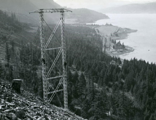
The CCR involved replacing existing electric transmission towers that were nearly a century old within the Port of Long Beach in Southern California. Replacement structures included four tubular steel poles and two lattice steel towers located on each side of the Cerritos Channel. The purpose of the project is to raise the electric transmission and telecommunication lines to accommodate taller, larger-capacity cargo ships entering the Channel. Foundation design was challenging across the board, but no structure faced the breadth of these challenges quite like the T2X tower located on the south bank of the Channel.
T2X is a four-legged lattice steel tower with a height of approximately 387 feet and a leg span of 60 feet square. The structure was heavily loaded; each tower leg foundation was required to support design compression, uplift, and shear loads of approximately 6770 kips, 3840 kips, and 580 kips, respectively, following incorporation of required factors of safety. A maximum displacement (vertical and lateral) of 1 inch was permitted under static loading conditions, with a requirement that the new structure not collapse and maintain its ability to carry normal working design loads after a design earthquake. In addition, the following conditions reported to exist in the area required consideration: highly corrosive and potentially contaminated undocumented fill soils, environmental sensitivities, and known and unknown underground utilities.
Based on project-specific subsurface data obtained prior to construction, and following over a year of technical review by the owner and a third-party entity, the contractor’s geotechnical engineering firm established that the design liquefaction depth at T2X was 86 feet. Seismically induced lateral displacement was estimated to be greater than 72 inches (i.e. > 6 feet) as a result of the structure’s proximity to the adjacent Channel. The result of this evaluation was that design of the foundation system would be required to resist and/or accommodate more than 6 feet of ground movement in the form of sliding towards the Channel due to seismically induced liquefaction of the underlying soils.
Site History + Geology
The history of development within the Port had a major impact on both design and construction of T2X’s foundation system. Up until 1897 when the Port was developed, the project site was a tidal mudflat and the structure location was underwater. In the early 20th century, the area was reclaimed by dredging the Cerritos Channel and filling adjacent areas to create what is now part of Terminal Island (Figure 1).
In 1936, oil was discovered within the harbor and erection of supporting infrastructure continued through the 1950’s. Oil extraction from the deep strata under the site led to one of the most accelerated cases of land subsidence on record. By 1958, the impacted area was about 20 square miles with a depression of up to 29 feet at the epicenter, which was very near T2X’s future location (Figure 2). In the 1960’s, the subsidence was halted by injection of water into the deep strata layers from which oil was extracted.
Regarding area geology, the Port of Long Beach lies within the coastal area of the Los Angeles Basin, which generally consists of a large, low-lying alluvial floodplain. The area development over the past century has resulted in soft/loose Holocene deposits being capped with a relatively thick layer of undocumented fill material that is generally characterized as highly corrosive with isolated areas of high contamination. Groundwater was generally coincident with the Channel, which had a water level of about 10 to 15 feet below the ground surface at the T2X location.
The project area is also seismically active with several notable earthquakes occurring within and adjacent to the Basin. The largest historical earthquake within the Basin was the 1933 Long Beach earthquake with a reported magnitude of 6.4. The epicenter of the more recent 1994 Northridge earthquake, with a reported magnitude of 6.7, was located just 35 miles from the project site.
Design Alternative
A host of design and construction challenges were contemplated and addressed during a design process that continually evolved and ultimately spanned from Fall 2018 to early 2020. The original design approach, consisting of partially cased cast-in-place concrete drilled shafts, was based on information available at the time of bid that indicated underlying dense sands of the Gaspur Formation would exist at a depth of about 70 feet, and that lateral spread magnitudes at the T2X location would be on the order of 1.5 feet. Construction associated with the original design included installation of permanent steel casing using vibratory methods through softer, liquefiable material to the dense sand layer beneath. The steel casing would be installed to a depth of about 70 feet and traditional drilling methods using slurry were to be implemented to extend the drilled shaft to the planned tip depth. The inclusion of permanent steel casing in the original design was primarily for excavation stability during shaft construction.
A subsequent geotechnical investigation, executed by contractor Longfellow Drilling, revealed that liquefiable soils extended deeper than originally anticipated. In general, the subsurface conditions consisted of up to 34 feet of undocumented fill underlain by estuarine/marine deposits to a depth of about 95 feet where dense granular soil of the Gaspur Formation was encountered. Design recommendations based on the updated geotechnical data resulted in a potential lateral spread displacement estimate of greater than 6 feet; this represented an increase of approximately 400% over the contractor’s original design assumptions.
It became apparent that the existing foundation approach was not feasible. The updated magnitude of lateral spread required that permanent steel casing extend to the shaft tip elevation and approximately 20 feet into the underlying dense Gaspur Formation. Permanent casing was no longer incorporated into the design for construction purposes only; it was now required for both design and construction reasons. Vibratory advancement of permanent casing through approximately 90 feet of liquefiable materials and up to 20 feet into the dense granular bearing layer presented a number of risks and led the team to reevaluate.
The project’s Foundation Engineer, Quanta Subsurface, collaborated with project foundation contractors, Longfellow Drilling and Malcolm Drilling, throughout the design process. This included iterative soil-structure analyses and working to establish the optimal foundation size based on design requirements, material and equipment availability, and cost. The final design included fully cased, large-diameter drilled shafts at each tower leg connected by a combination grade- and tie-beam system. Full size grade beams would be constructed perpendicular to the Channel slope, and tie beams parallel to the Channel face. The grade- and tie-beam system was specifically designed to address the liquefaction induced lateral spread in a four-legged structure. The final design was not developed to resist all lateral movement; instead it would result in uniform lateral displacement, enabling the structure to maintain normal working design loads after a design earthquake.
Other foundation systems and ground improvement methods were considered; specifically, foundation systems that incorporated deep soil mixing. These were considered in multiple combinations, including use in conjunction with drilled shafts to remove the need for fulllength casing. Ultimately, deep soil mixing was deemed unfeasible due to potential environmental impacts, known and unknown underground utilities, the volume of required materials and the spoils generation, cost, and the lack of Port approval.
Shaft Construction
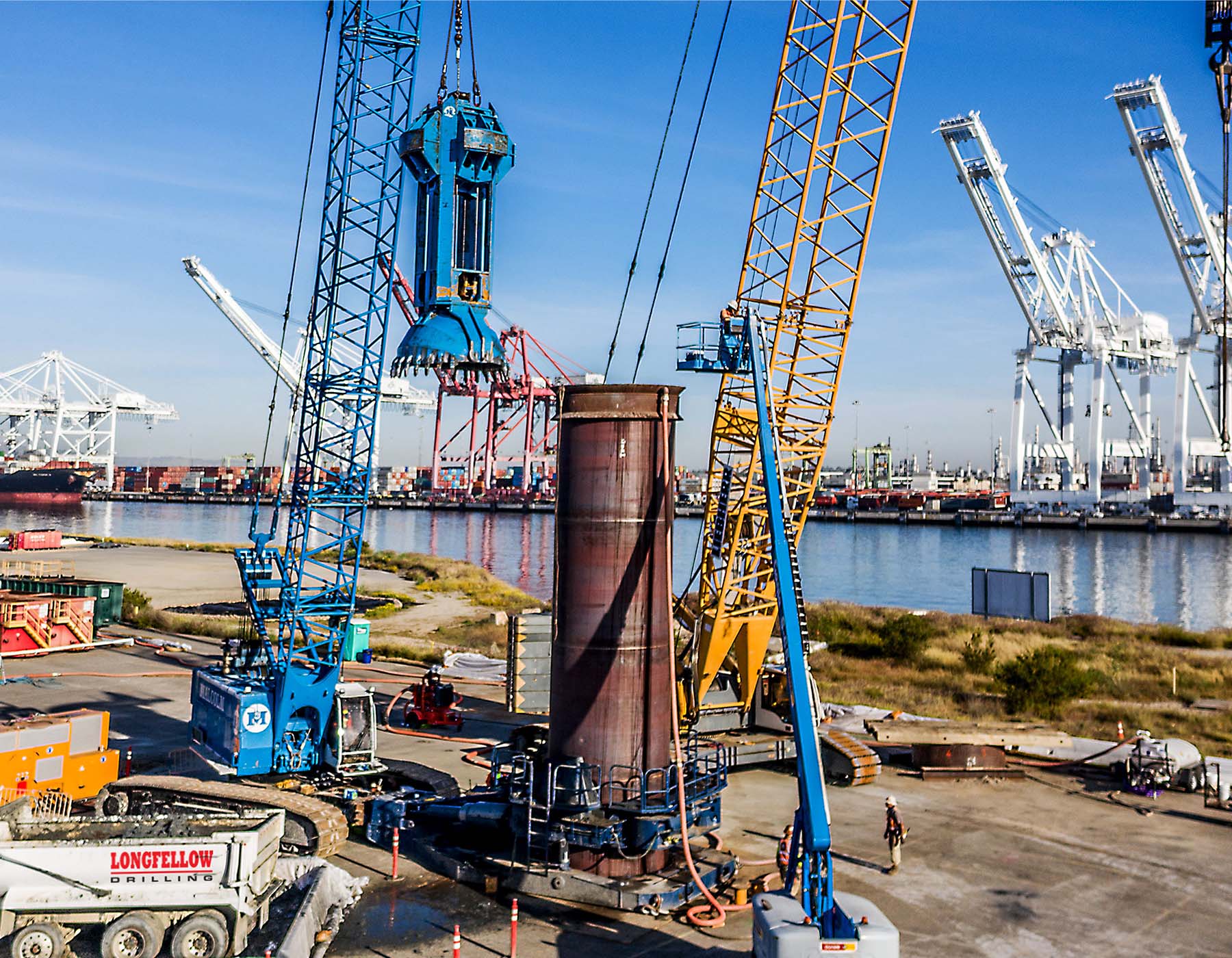
The shafts were designed with an outside diameter of 9.84 feet (3 meters) and a minimum embedment depth of 115 feet below the ground surface. For both design and constructability reasons, designs incorporated permanent, 1.25-inch thick, full length steel casing. Casing was advanced in sections, requiring specialty welding with mag-particle testing, and a crane-suspended spherical grab was used to excavate overburden material. Upon completion and final cleanout, the 54,000-pound reinforcement cage was hoisted and set into position. Precise anchor bolt placement was critical to ensuring the foundations at each of the four tower legs aligned with the grade- and tiebeam system. Concrete placement was completed using a tremie pipe and concrete pump truck to the construction joint location. Post-construction QA/QC inspections were performed, as well as project-required Gamma-Gamma Logging to verify the integrity of the shaft.
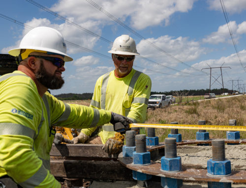
Construction of the grade- and tiebeam system required mass excavation, setting the 16,500-pound anchor bolts, civil grade beam steel reinforcement placement with anchor bolts in place, formwork and concrete placement. The anchor bolt tolerances, less than a fraction of an inch, were maintained by performing multiple survey checks to each bolt cluster to verify location from the center of the tower and in relation to each other. In addition to the lateral location of the anchor bolt cluster, a custom heavy-duty support system was fabricated to span the large grade beam excavations while ensuring the anchor bolts maintained design elevation tolerances. The concrete placement required for construction of the grade- and tie- beam system totaled approximately 500 cubic yards and was performed monolithically. Concrete placement was completed using multiple concrete pump trucks to ensure precision placement pace and consistent concrete elevation throughout. This was crucial to prevent failure of the formwork system and to promote uniform concrete hydration.
Project Summary
All foundation construction was successfully completed, and the upgraded infrastructure will continue to service the region with electricity while facilitating the Port’s expanding operations through the end of this century. Although seismic and liquefaction concerns were primarily discussed, environmental protections, underground utilities and potentially contaminated soils presented additional hurdles that the team worked to successfully overcome. It should also be noted that construction began in early March of 2020 at the onset of Covid-19 shutdowns, creating a highly uncertain work environment and requiring further collaboration among team members to ensure employee safety and an overall successful project outcome. As a whole, project challenges were worked through collaboratively during the design phase and allowed construction to be smoothly and efficiently completed.
Published by Foundation Design


