Design and In-Construction Geologic Characterization of Micropiles to Support a Historic Transmission Line Upgrade in the Step Talus and Basalt Slopes of the Columbia River Gorge
Originally constructed between 1939 and 1941 as part of Franklin D. Roosevelt’s New Deal programs, the Bonneville to Hood River 115 kV Transmission Line required an infrastructure upgrade to remain reliable and in-service. The line traverses the rugged landscape of the Columbia River Gorge on the Oregon- Washington border, featuring steep, talus slopes; uneven, rocky terrain; and a variety of environmental sensitivities. This paper details the design and construction of 27 micropile foundations for new, fire- hardening steel poles through a particularly challenging stretch of the alignment. The difficult access and environmental constraints at these sites designated them as helicopter-accessible and precluded the collection of detailed geotechnical information prior to construction. Micropiles provided a viable foundation alternative due to their portability and flexibility during construction. Detail will be provided on the extensive preliminary desktop study performed, as well as the process of developing engineering designs to successfully accommodate for variability and unknowns in complex geological conditions. With an increasing number of electric power projects traversing challenging terrain and facing similar obstacles, this project stands to provide valuable lessons learned to the industry.

Authors:
Kevin Haiar, P.E., Crux Subsurface
Brian J. Olson, C.E.G., Crux Subsurface
Introduction
When overhead electric power projects traverse remote and challenging terrain, micropile foundations become desirable as a flexible and portable installation option. The Bonneville to Hood River 115 kV Transmission Line served as a paradigm for micropile construction in rugged topography where geologic conditions changed with depth, necessitating design and construction flexibility to accommodate for the uncertainty. Limited access to structure sites also created challenges during the foundation design phase, as ground-level reconnaissance was inhibited. Desktop-level data acquisition and in-construction soil characterization methods were more heavily relied on as a result. Ultimately, the project overcame a variety of unique design and construction challenges to successfully install 27 micropile foundations.
Historic Background
The Bonneville-The Dalles Transmission Line was originally constructed by the Bonneville Power Administration (BPA) between 1939 and 1941 to distribute electricity generated from the Bonneville Dam to the growing rural communities of Northeastern Oregon. The western-most 22.61 miles of this line is known as the Bonneville-Hood River segment, constructed through a distinct area of variable and difficult- to-access terrain along the southern shores of the Columbia River. The transmission line right-of-way (ROW) is located entirely within the Columbia Gorge National Scenic Area.
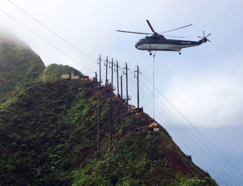
Historic documentation of the construction phase is limited, but a number of historical photographs have been preserved by BPA and the Library of Congress which capture parts of the process. The challenging topography and site access are evident in these photographs.
State of the art engineering in 1940 consisted of steel lattice structures, designed for either rock or soil embedment. Foundation drawings provide some indication of the designs, with hand-excavated shafts four feet in diameter and up to nine feet deep. The line was energized on May 24, 1941 and remained in service for over 75 years. A total of 68 structures utilized a unique modular H-frame design, with a relatively slim appearance that quickly oxidized and blended into the landscape. The aging infrastructure ultimately required an update, and BPA announced the Transmission Line Rebuild and Access Road Improvements Project in October of 2018. The 68 lattice steel structures would be retired, with new engineered steel and wooden poles supporting the reconductored 17-mile segment.
Project Details
Although access to portions of the line have improved since original construction, pre-construction site tours were still performed via helicopter to provide the best vantage point for many of the harder-to-access
locations. Access constraints also prohibited the acquisition of geotechnical data along much of the alignment. Pre-construction geotechnical investigations were concentrated on the eastern end of the alignment, where road improvements had been made for recreational use and conventional drilled shafts were most likely to be installed.
Construction was awarded in February of 2019, and included a variety of foundation types and contractors to ensure the optimal foundation type could be installed based on line requirements, subsurface conditions, cost, and schedule. A combination of direct-embedded and drilled shaft foundations was designed for the majority of structure sites, where either vehicular access existed or could be reasonably improved as part of the project. At 26 of the 68 structure locations, including 25 monopoles and 1 H-Frame, the conditions had not changed considerably since original construction. Here, the project team mobilized to design micropile foundations suitable for helicopter construction methods.
Geologic Mapping and GIS
Prior to developing foundation selections, the foundation designer thoroughly reviewed available geologic mapping and aerial imagery to determine which foundation types would be most suitable for local geological conditions. Geologic mapping and associated literature were compiled and layered into a Geographic Information System (GIS) platform, with multiple generations of geologic maps layered and cross-referenced with the coordinates of proposed micropile foundation sites.
Ground slopes, surficial soils, groundwater conditions, and expected bedrock depths and types were outlined for each site. With geotechnical boring data lacking, best-guess subsurface profiles were outlined at each site to facilitate design. This process provided a basis for design and quantified the areas of highest uncertainty, where in-construction observation would be vital to accommodate for the significant subsurface variability.
Based on the preliminary geologic and geotechnical review, the 26 structure sites were categorized based on the expected subsurface conditions. The three general categories developed were:
Bedrock Sites – Maps and surface exposures indicated the Grande Ronde Basalt of the Columbia River Basalt group was expected to be the most common bedrock type mapped. Maps also indicated granitic rock would be encountered at depth in a lesser percentage of the foundations, generally beneath the Shell Rock talus area for the westernmost structure foundations. Micropile bond stress values for these bedrock types were well established and design parameters were relatively well defined. Variations were limited to the depth and weathering profile of the bedrock, as it was expected to vary considerably, sometimes across an individual tower footprint.
Talus Sites – Talus are an outward sloping and accumulated heap or mass of rock fragments of any size or shape (usually coarse and angular) derived from, and laying at the base of, a cliff or very steep, rocky slope. They are formed chiefly by gravitational falling, rolling, or sliding. In this area of the Columbia Gorge, talus consisted of angular gravel to boulder-sized basalt and granitic clasts shed from the elevated cliff areas south of the structure sites. Although the interlocking angular deposits provide a high degree of global slope stability, the materials at the surface can be loosened when loaded by equipment or even heavy foot traffic. Maps and field reconnaissance indicated at least one third of the micropile foundation sites had the potential to be founded in this geology. These materials pose challenges to micropile construction for a variety of reasons, one of which is that bond stress values are not well established. Clast size ranges from gravel to boulder, and the unit often masks underlying debris- or mud-flow deposits. Voids within the larger clasts would also pose a challenge during drilling and grouting. A verification test program to characterize this material was developed and executed prior to construction to assist in accommodating for unforeseen vertical variations in composition.
Soil Sites – Soil sites where bedrock outcrops or talus deposits were not evident in site reconnaissance also necessitated micropile design flexibility. In some cases, surficial talus deposits can hide buried finer grained soils and debris- or mud-flow deposits. In other areas, nearby bedrock outcrops or geologic map indications of bedrock were misleading, and deep soils would necessitate longer, specialized micropile bonds. In these cases, piles would need to be deepened to establish bonds in underlying bedrock, or pressurized Type B or Type D bonds would be required. Pre-construction desktop studies suggested soil deposits would be the least common category among the three.
Geotechnical Profiling and Analyes
With a minimal amount of soil boring information, the project team developed preliminary subsurface profiles based on regional geologic mapping, and internal soil/rock strength data derived from nearly 15 years of construction experience and micropile testing programs. For much of the line, basalt bedrock outcrops noted during field mapping provided good design certainty. However, overburden materials included rock talus and soil deposits. The depth and composition of these strata were not well defined during initial foundation design, resulting in baseline assumptions being made from geologic map units, desktop study, and helicopter reconnaissance.
Foundation Design
The micropile foundations were designed and developed based on the maximum ground line reactions provided by BPA, which ranged from approximately 350 to 2900 kN-m (250 to 2140 k-ft). The designs involved piles arranged in a circular pattern with between four and eight piles per foundation. The foundations were required to consider a depth to ignore (DTI) allowance to account for scour, surficial instability, and sloping ground in accordance with BPA specifications. Models were developed with flat ground and extended stick-up reflecting the prescribed DTI value. Additionally, each site was modeled with
the maximum estimated slopes and pile stick-up to verify that DTI allowance had captured actual conditions. The piles were battered away from foundation center to provide additional lateral support and to aid in pile separation at depth to avoid group effects in the bond zone. Lateral stiffness models using P-Y curves were used in design to capture foundation stiffness.
Foundation schedules were developed for each site, with designs enveloping the expected conditions based on the geologic desktop study, geotechnical profiles, and analysis. The schedules provided foundation options for the varying topography, site slopes, and anticipated subsurface conditions, allowing the contractor to react to varying subsurface conditions as they arose without the need to revisit the design. Professional geologists were onsite to assist the drilling contractor in characterizing and interpreting the subsurface conditions per the foundation schedule, plans and specifications.
Steel Pile Caps
Steel pile caps were utilized partly because they could be set in a single helicopter trip, but also for their ability to be fabricated offsite in parallel with other construction activities. The caps consisted of a single or double round flat plate with pre-cut holes for micropiles and structure anchor bolts. Customized and patented rotating spin drills were used to install the piles accurately for cap alignment, but some oversizing of the micropile holes was also allotted for fit up. The caps were designed using finite element analysis (FEA) to model the varying loadings, pile layouts, and stresses more accurately. The models accounted for specific pile geometries and the associated components, as well as the potential offset or misalignment of individual piles. FEA was used to validate performance, including plate stresses, deflection, yielding and buckling. This design process has been validated on multiple projects with full-scale load testing in the field.
Single plate pile caps ranged in thickness from 6.35 to 10.8 cm (2.5 to 4.25 in) and double plated caps ranged from 12.7 to 14.0 cm (5 to 5.5 in), while cap diameters ranged from 132.1 to 208.3 cm (52 to 82 in). The pile cap design is specifically fabricated to serve as a reaction frame for load testing of individual piles when possible; typically for foundations with more than four piles. This serves as a tangible benefit to projects with steep slopes and/or unpredictable subsurface conditions in multiple ways. It eliminates the need to set up reaction cribbing in the challenging environment; it creates a safer environment for the contractor; and it allows for relatively easy and efficient testing of any piles that experience anomalies or otherwise require unplanned load testing.
Geologic Monitoring and Characterization
During drilling at each structure, geologists representing the Foundation Engineer of Record (EOR) were onsite to work with the Micropile Contractor, confirm the subsurface conditions, and properly assign cased zone and bond zone IDs. Standard Penetrometer Test (SPT) sampling was performed in general accordance with ASTM D1586, and encountered materials were classified in general accordance with ASTM D2488. After the characterization of soil and rock profiles, but before reinforcement placement, individual micropile geometries were recorded, confirming the scheduled depth requirements. Because micropile performance also relies on a relatively unobscured grout-to-ground contact, appropriate cleaning methods were performed per FHWA (2005). The project team utilized a downhole camera system, which was specially adapted for micropile diameters to further assess borehole conditions and qualify grout-to-ground strengths.
Detailed observation and inspection documentation were completed to ensure micropiles were installed in accordance with project plans and specifications. With a considerable degree of uncertainty in conditions at several sites, this was particularly crucial to successful installation. While BPA provided performance oversite, quality assurance (QA) was performed by registered field geologists representing the Foundation EOR. In addition, quality control (QC) tasks were largely performed by the Micropile Contractor. This arrangement facilitated design criteria checks in concert with adjustments to means and methods as needed.
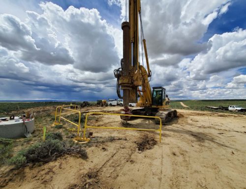
Foundation Construction
The Micropile Contractor provided customized, patented drills that could be broken into helicopter-portable components and transported to foundation sites. Leveling platforms provided stable surfaces for equipment and materials, neutralizing the steep slopes and minimizing excavation requirements in the rugged terrain. The platforms also provided a template for the rotating micropile drill, allowing for all piles in each array to be installed without relocating the drill or requiring helicopter support.
Construction was frequently impacted by short, unpredictable schedule windows due to the high winds and generally dynamic weather conditions of the area. To minimize schedule impacts, crews needed to be prepared to move on and off foundation sites quickly as these windows allowed. The use of steel pile caps contributed immensely to this flexibility, as they were fabricated offsite and could be installed relatively quickly with one helicopter trip. Compared to concrete caps, the steel caps reduce helicopter use by an average 74% and onsite labor time by an average 64%. These reductions substantially limited overall exposure to weather risk.
Load Testing Programs
Micropile load testing programs were critical to the project and designed consistent with selected safety factors for the grout-to-ground bond strength used in capacity calculations. For the sites underlain by variable talus stratigraphy, deflections measured through verification and proof testing provided the best estimates of structural deflections.
This project included both a pre-production verification test program as a first order of work under the construction contract, as well as a production proof testing program completed during construction. For verification testing, two sacrificial micropiles were installed in locations established by BPA with the intention of defining the bond zone strength for talus materials as well as confirming the adequacy of the Contractor’s installation methods. SPT sampling, geologic logging, and downhole camera video were utilized to document the geotechnical conditions in each of these sacrificial piles. The construction methods mimicked the production piles, including the use of grout socks to combat excessive grout loss in the porous talus materials.
Verification test programs like this are most commonly performed on sacrificial piles prior to construction. They can provide benefit by optimizing engineering designs through defining grout-to-ground bond stresses of specific rock units, consistent with the engineering practice outlined by the FHWA. However, when a high degree of geologic uncertainty exists and geotechnical bond units may vary, either due to variations inherent in the geologic unit or distance between the sacrificial test locations, an in-construction proof testing program can serve to provide additional quality assurance. Proof testing is typically conducted on a percentage of the total production piles being installed. It not only verifies the consistency of the construction procedure, but also confirms that micropiles are not drilled and grouted in rock or soil weaker than the bond strengths assumed.
On this project, proof testing was performed on all foundations where talus or soil bonds were installed. Test results highlighted three structure locations where the talus strengths differed considerably from that of the verification test program and required some design adjustment. Consistent with micropile construction methodology outlined by the FHWA, installation methods were modified by either changing micropile types to incorporate pressure grouting or increasing bond lengths/pile depths. This flexibility involving the same installation equipment and materials allowed for minor adjustments during construction to accommodate these fairly significant deviations.
Project Completion
The Bonneville to Hood River Transmission Line was officially energized in the Fall of 2020, with micropiles providing a flexible solution to major project challenges at 26 structure locations. Most notably, the variable soil, talus and bedrock subsurface profiles necessitated foundation designs that accommodated for subsurface uncertainty as well as the difficult access. Verification testing programs prior to construction, site characterization during construction, and proof testing of production piles were crucial to both efficient foundation installation and subsequent performance.
The foundation design and construction practices implemented on this project successfully accommodated a condensed schedule due to multiple environmental and permit-related constraints, which are not uncommon to transmission line projects through sensitive areas. As the electric power industry sees an increasing number of similarly challenged projects, the successes of the Bonneville to Hood River Transmission Line can serve as a valuable template.
References
Historic American Engineering Record (HAER) - Library of Congress, undated, Bonneville Project, Bonneville-Hood River Transmission Line, Bonneville Dam Powerhouse 1 to Hood River Substation, Bonneville, Multnomah County, OR, documentation compiled after 1968, Call Number HAER OR-11-G, https://www.loc.gov/pictures/collection/hh/item/or0637/
Mathieson M.L., Mitchell, C., Robertson C.A., Rustvold J., 2004, Micropiles to Support Electric Power Transmission Towers Proceedings of the 29th Annual Conference on Deep Foundations, 2004, Vancouver, British Columbia, Canada "Emerging Technologies", (DFI article #1243; publication #68 (AM-2004)
Thompson, F., Salsbury N., Khattak A., Hastings, A., Foster, M., 2009, Integration of Optimum, High Voltage Transmission Line Foundations. ASCE Proceedings of the 2009 Electrical Transmission and Substation Structures Conference.
Turner, K.A., 1996, Landslides: Investigation and Mitigation, Chapter 20 - Colluvium and Talus Transportation Research Board Special Report, Issue No 247, ISBN 0-309-06151-2.
U.S. Department of Transportation FHWA, 2005, Micropile Design and Construction Reference Manual for Course 132078, Publication No. FHWA NHI-05-039, December 2005
Published by Deep Foundations Institute