Interactive Quality Assurance to Identify Coal Seams During Foundation Construction
Abstract
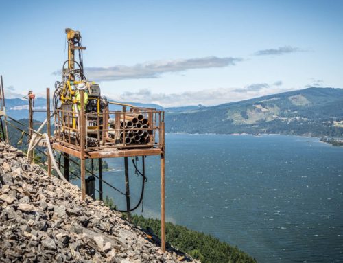
The Aeolus – Jim Bridger Transmission Line Project is located in southern Wyoming, home to some of the largest coal seams in the world. Coal seams present unique challenges to underground construction, as they are at high risk of coal-seam fires and do not provide a reliable bearing stratum. Accurate identification of these hazards was essential for reliable design and successful construction of foundations on this project; however, environmental restrictions and other protections created short time frames to access several sites. Coupled with a firm construction deadline, this meant that a comprehensive geotechnical investigation prior to construction would not be possible. This paper presents the project as a case study, and details how an Engineer-Procure-Construct (EPC) contracting format supported by a comprehensive Quality Assurance (QA) program provided a solution to the defined challenges. It describes the initial design process using incomplete geotechnical data and explains how the developed QA program verified design assumptions and reduced geotechnical risk through early identification of geologic conditions during construction. Specific examples will be given, and industry implications will be discussed.

Authors:
Christopher Lawler, P.G. Crux Subsurface
Matthew Runion, P.E., Crux Subsurface
Introduction
Long linear infrastructure projects like those found in the electric power industry present unique challenges to the design and construction of deep foundations. A single alignment can traverse hundreds of miles and encompass a diverse range of subsurface conditions. Comprehensive pre-construction geotechnical investigation programs may be unfeasible due to economic and regulatory factors, resulting in these programs being implemented simultaneous to foundation construction. In these instances, a proactive and dynamic QA plan can be instrumental to the success of an EPC contracting format, and add substantial value to the project. It allows foundation designs to be adjusted to accommodate changes in conditions while minimizing or eliminating associated construction downtime.
Paired with a collaborative EPC team, the comprehensive QA plan developed for the Aelous - Jim Bridger Transmission Line Project played a pivotal role in the identification of unanticipated or problematic subsurface conditions, and ultimate on-time completion of construction.
Project Challenges
The project consisted of a new high-voltage electric transmission line in southern Wyoming. The approximately 138-mile line includes both 500 kV and 345 kV sections, and a total of 551 structures. 518 of the structures are four-legged lattice steel towers supported on drilled shaft foundations, and 33 are a combination of direct-embedded H-frame poles and drilled shaft supported three-pole structures.
Challenging subsurface conditions in the area played a pivotal role in structuring the EPC contract and were a major factor in foundation design. As the largest producer of coal in the United States, Wyoming is home to some of the largest coal seams in the world. Coal seams present unique challenges to underground construction as they are at risk of coal-seam fires and do not provide a reliable bearing stratum. When coal is encountered, foundations should ideally be extended beyond coal material and into a competent bearing stratum.
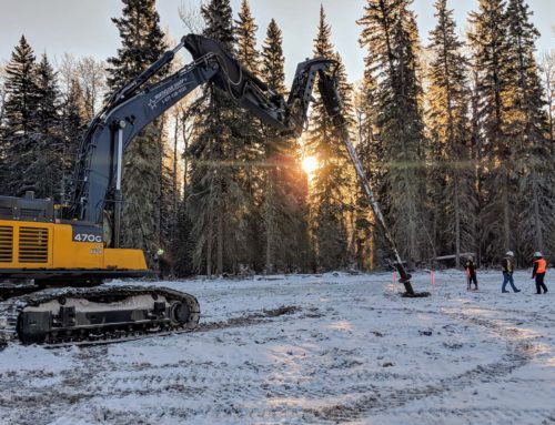
A geotechnical investigation was commissioned prior to construction, but was limited in scope. As is common in the electric power industry, several structure sites were subject to biological variance restrictions and were not accessible prior to the planned April 2019 construction start. Delaying construction to conduct a supplemental investigation was not an option as foundation work was required to be complete before the first major snowfall. Given the large scope of work and somewhat unpredictable end date, it was determined that any subsequent geotechnical data would need to be obtained during construction.
EPC: Transferring Risk
Under a traditional design-bid-build contracting format, the limited geotechnical information and increased potential for encountering subsurface challenges on this project would have presented a high-risk situation for the owner. A foundation design package would have been released to bid, and the owner would have taken on responsibility for the adequacy of the designs. Any changes in conditions encountered during construction would have resulted in change orders with the potential to delay construction and increase costs.
Under a lump sum EPC contract, the risk on this project was effectively transferred to the selected EPC team, including the Engineer and Contractor, which assumed responsibility for developed designs and pricing.
Design Approach
The Owner provided preliminary foundation design takeoffs at the bid level and the EPC team performed engineering analyses to identify potential areas of risk and opportunity. Design profiles were developed from provided geotechnical data, which included 118 soil borings. Field and lab test data gathered from the soil borings were evaluated to determine suitable strength and stiffness correlations for soil and bedrock on the project. A geologic desktop study was then performed, focusing on the various surficial and bedrock geology mapped along the alignment. The desktop study was key to establishing a range of potential geotechnical conditions at sites where geotechnical data was sparse, and to identifying locations where coal was probable.
A risk assessment was conducted at locations where risk and uncertainty were identified in the subsurface conditions. This was intended to capture the impacts geotechnical variability might have on the foundation design. Where coal was expected to be encountered, foundations were designed to satisfy strength and service requirements considering a strength of coal material that was reduced from what was reported in the project-specific geotechnical reports. If coal seams were encountered in construction, the excavation would need to be extended to a minimum of one foot beyond the coal seam to provide sufficient bearing capacity in competent material.
Foundation designs are often developed irrespective of tooling and construction approaches used by the awarded foundation constructor. Early collaboration within the EPC team identified the Contractor’s preferred tooling sizes and construction approaches for unstable excavations or when encountered soil conditions varied from the design expectations. This information directly influenced the design approach, and final foundation designs were developed with mobility and adjustability in mind. This type of forward thinking is a major benefit of the EPC structure, as it enables the Contractor to shape foundation designs with construction efficiencies in mind.
Early review of Owner standards and project requirements allowed the EPC team to identify prescriptive requirements which could have major impacts on construction productivity. One such instance was an initial requirement to place concrete within 12 hours of foundation excavation. Due to the remoteness of many foundation locations, it was likely that excavations at a given structure site may not have concrete available until the following day. Collaboration with the Owner resulted in relaxing the timeline to 24 hours, with engineering inspection required for any excavations that did not meet this specification. This modification resulted in more efficient construction planning, reducing risk to the EPC team and the overall construction schedule.
The final design package consisted of drilled shafts 3 to 5 feet in diameter and up to 46 feet deep to support lattice tower; drilled shafts 7 to 9 feet in diameter and up to 22.5 feet deep to support tubular steel pole
structures; and direct-embedded pole excavations 5 feet in diameter and up to 21.5 feet deep. Geotechnical strength was evaluated utilizing a Load and Resistance Factor Design (LRFD) approach. Performance was evaluated at factored loads and allowed for a maximum total deflection of four percent of the foundation diameter, a maximum total rotation of one degree, and a maximum vertical settlement of one inch. Drilled shaft reinforcing steel was designed in accordance with ACI 318-14 and ACI 336.3R-14.
Mitigating Risk Through QA
Foundation designs allowed for flexibility based on conditions encountered in the field; the success of which hinged on the development and implementation of a robust, proactive QA program. Licensed, professional geologists with prior foundation construction oversight experience would be onsite to oversee the Contractor’s Quality Control (QC) program, verify encountered geotechnical conditions against the design assumptions, and assist in anticipating and facilitating required design changes. The program was tailored to allow for real-time design support throughout construction with little to no delay, and was accomplished by establishing an interactive network between the Owner, Engineer, Contractor and QA/QC team.
The risk assessment performed during the initial design phase provided the Engineer with an understanding of the impact, in general terms, that specific changes in geotechnical conditions could have on foundation designs. This allowed the EPC team to prepare for a much broader range of possibilities, and substantially streamlined the construction process. Communication and transparency between all project members were vital to identifying and classifying subsurface conditions, managing expectations, and executing any design adjustments in a timely manner.
As a proactive measure to avoid schedule delays, the QA program was also heavily intertwined with the supplemental geotechnical investigation. Sites were given priority based on planned construction schedules and deductions made from analyses at previous sites. As an example, if a coal seam was encountered at a site, the team could review the size and orientation, and conclude with some accuracy whether that particular coal seam would impact subsequent sites. The western portion of the project featured fairly flat topography and allowed for a simple analysis of coal seam behavior, whereas the eastern portion featured more undulation, requiring more involved and subjective projections. Sites that were suspected to be impacted by encountered coal seams could be prioritized for additional geotechnical data, allowing any required design changes to be made prior to construction instead of during.
Information from historical aerial images and mine data was also considered. As an example, coal mining was particularly prevalent near the eastern portion of the alignment and further review of the data revealed several areas of concern at or near structure locations. One site in particular rested directly on top of an overburden pile from strip mining in the early 1900’s. As shown in Figure 3, aerial images from the 1990’s show the overburden much more clearly than recent images, where the site has been covered in vegetation. The analysis allowed the team to identify a potentially problematic area ahead of construction. This site was prioritized in the supplemental geotechnical program, and the acquired data allowed Engineering to make the necessary design adjustments to accommodate the unconsolidated and uncontrolled overburden.
The foundation drawing set included soil profile descriptions that represented the conditions assumed at each structure location. This provided the Contractor and the QA personnel a quick reference during construction as to assumptions made during design. QA made observations onsite and relayed any change in conditions to Engineering in real-time. The Contractor knew immediately when design alterations were required to meet encountered conditions, and updated designs were often released within a few hours of change notification. Differing from past programs, which tried to classify subsurface material extracted from the excavations in too much detail, the EPC team focused this program on the behavior of the excavation as it was being drilled. With a rock auger of this size, it was difficult to gain much from analyzing the cuttings produced. Instead, the program focused on monitoring and analyzing the shape and characteristics of the excavation (i.e. sidewall sloughing, swelling, and overall stability) and performance of the drilling equipment. This method of characterization contributed immensely to consistency across the project and is a major step toward standardizing a QA program for future endeavors.
Construction
Design alterations resulting from a change in conditions included eleven sites where the encountered soil profile did not match what was anticipated; four unexpected coal seams; two coal seams that were larger than anticipated; and one instance of unexpected groundwater. Two of the most extreme examples will be described as Site A and Site B.
At Site A, a large unexpected coal seam was identified by QA personnel and communicated to Engineering. The thickness, orientation, and depth of the seam varied at each of the four lattice tower legs, and the foundation designs were analyzed separately.
Original drilled shaft designs at all four legs were to be 3 feet in diameter and 15 feet deep. At leg one, the coal seam extended from 7 to 14.5 feet below the ground surface, and the design was required to be extended 1.5 feet to an embedment depth of 16.5 feet. At leg two, the coal seam extended from 6.5 feet to 13 feet below the ground surface, and the design was required to be extended 1 foot to an embedment depth of 16 feet. At legs three and four, a 4- to 5-foot coal seam was encountered at depths of 17.5 feet and 18.5 feet respectively. Analysis of the shafts at these legs showed sufficient geotechnical resistance when the shaft was extended to one foot below the bottom of the coal seam, per the project requirements.
The analysis at Site A was conducted during construction, with information continuously flowing between QA and Engineering. QA monitored drilling activities, characterized auger cuttings, and communicated pertinent data to Engineering. Engineering then assigned suitable geotechnical strength parameters to bearing material and provided QA with direction on how to proceed. For each leg, engineering instruction was efficiently turned around within two hours of receiving QA data to ensure construction schedules remained on track.
At Site B, the encountered soils did not match the assigned soil profile. QA personnel classified them as loose silty sands, which did not meet the required soil profile for very dense, non-cohesive soils. These conditions were fairly consistent between the four tower legs at this location. The pre-construction design, anticipating very dense material to depth, specified a 3-foot diameter shaft embedded 15 feet below the ground surface.
The change in condition was identified, characterized, and communicated to Engineering. Engineering provided a response within the hour, specifying that the shaft be extended 6 feet to a total embedment depth of 21 feet. Drilling continued until unanticipated fresh, strong quartzite was encountered at a depth of 20 feet. Once again, the change was identified, characterized, and communicated to Engineering. A second redesign was efficiently developed factoring in the tooling and materials the Contractor had readily available. The shaft diameter was ultimately increased to 3.5 feet. This change allowed for a 20-foot shaft depth, eliminating the need to drill further through the quartzite while still meeting required capacities.
Foundation construction began in April of 2019 and was successfully completed in mid-December, before the area received its first major snowfall.
Summary
The Aeolus – Jim Bridger Project demonstrates the cost and schedule benefits a proactive and interactive QA program can provide to foundation design and construction under an EPC contracting format. It allowed for preliminary designs to be developed and construction to begin despite limited geotechnical data in an area known for subsurface hazards. It provided insight into when and where additional data should be collected in advance of construction, and guidance when conditions encountered during construction did not match those anticipated. The program extended from design to construction and facilitated seamless interaction between the EPC team, leading to the ultimate on-time completion of the alignment.
Though this type of program is heavily reliant on the structure and increased communication of an EPC contract, the electric power and other industries are seeing an increasing number of these types of arrangements. Firm project deadlines coupled with access restrictions and variable subsurface conditions are demanding more integration between design and construction, which opens the door for preemptive, collaborative QA programs.
Las Vegas Wash Tunnel, Las Vegas, Nevada
The Las Vegas Wash Tunnel, also referred to as the Southern Nevada Water Authority (SNWA) East Valley Transmission – Phase II Tunnel (Contract 170A), was built by Affholder, Inc. for SNWA. The prime civil designer was Boyle Engineers, the tunnel designer was Brierley Associates, and the geotechnical engineer was Converse Consultants. Crux Subsurface was subcontractor to Affholder providing horizontal confirmation test borings to allow implementation of a contractor value engineering proposal to substitute a TBM for drill-and-blast, and for pre-tunneling grouting of a fault zone with anticipated high ground water inflows.
The Las Vegas Wash Tunnel is an approximately 440 m long, 3 m diameter water transmission tunnel connecting cut-and-cover pipeline segments either side of Las Vegas Wash. Tunneling was designed beneath the wash to avoid working in a sensitive desert wash environment, and to site the pipeline well beneath potential flood and erosion impacts within the wash. Because the pipeline was deepened into a tunnel segment in this area, ground water issues related to perchlorate contamination merited pre-excavation grouting to minimize handling of contaminated water.
Preliminary design of the tunnel evaluated both mechanical and drill-and-blast construction alternatives, however, the owner elected to bid the work as drill-and-blast only. Affholder proposed a TBM alternative and offered to core the alignment from both shafts to confirm baseline conditions. This involved drilling two approximately 230 m long, HQ triple tube rock core borings overlapping at the tunnel midpoint. The proposal included a provision to take elements of the differing site conditions clause off the table in exchange for approving the change in tunneling method.
Bedrock conditions consisted of various Tertiary volcanic and sedimentary rock strata of the Horse Springs and Thumb Formations and including interbedded sandstone, siltstone, limestone, claystone and andesite. Rock quality varied from very poor to excellent and on average was fair based on RQD. Drilling was performed using a custom-built rig set up for shaft work with special hydraulics that allow for essentially “wrenchless” drilling. The north shaft and south shaft were approximately 5 m and 7 m in diameter, respectively. The minimum desired shaft diameter for this type of work is approximately 5 m. Assembling the drill rig in the north shaft involved very close tolerances and required lowering the drill rig into position on end rather than upright as shown in Figure 4. Figure 5 shows the drill setup in the shaft during production coring and grouting.
Because of the importance of the drilling to Affholder’s risk management for the project, they required Crux to meet a deviation criterion of less than or equal to 0.5 m deviation per 230 m hole drilled. Frequent deviation surveys to monitor the locations of the coreholes and corrections to meet the deviation criterion were made. The subcontract agreement included provisions to redrill at no additional cost if the deviation criterion was not met. Meeting the criterion required to occasional use of steerable mud motor tools to reestablish line and grade and redrilling short sections of previously cored hole.
The core borings from both shafts were completed successfully within the deviation criterion. Fault zone grouting was performed using the investigation core holes using cement grout for permeation grouting. In addition, three additional core holes were drilled to implement additional grouting prior to tunneling. The whole specialty drilling and grouting subcontract resulted in 890 m of HQ-3 diamond core drilling and sampling and approximately 50 m3 of cement grout placement over 440 m of tunnel from five coreholes for an approximate total cost of $500,000. This effort allowed approval and implementation of the substitution of mechanical excavation with a TBM for the specified drill-and-blast approach.
In addition, it provided all parties with additional geotechnical information in the form of continuous core through the entire length of tunnel for refined planning and risk management purposes. The drilling also allowed access to perform ground modification in advance of tunneling, thereby eliminating grouting from the tunneling cycle to increase efficiency.
Cahaba Sewer No. 4 River Crossing, Birmingham, Alabama
This final case history example illustrates using horizontal drilling by the contractor strictly as a risk management tool in a case where he felt he had insufficient geotechnical information to proceed with a portion of the work that might be unsafe. The Cahaba Sewer No.4 Tunnel involved an approximately 50 m long river crossing beneath the Cahaba River near Birmingham, Alabama. Environmental and private property access limitations during design performed by Hendon Engineering Associates precluded obtaining test boring information immediately beneath the river. The available geotechnical information indicated approximately 5 to 10 feet of competent sandstone bedrock cover at the river crossing.
Affholder, Inc was the tunneling contractor. Brierley Associates worked for Affholder as geotechnical/tunneling consultant during construction. Crux worked as a specialty drilling subcontractor to Affholder, conducting supplemental horizontal geotechnical investigations prior to attempting the crossing.
During construction, Affholder was able to negotiate access to the river to drill conventional test borings from a barge to confirm bedrock conditions at the crossing prior to arrival of the TBM. A number of vertical borings were drilled that confirmed the competent sandstone conditions that were anticipated, but with cover as little as 1.5 m. Alternative alignment evaluations and stability analyses confirmed making the crossing safely from a structural standpoint, but uncertainty remained about possible ground water inflows. Any kind of breach connecting to the river could have resulted in potentially fatal inflows to the tunnel.
Affholder elected to sink a small, 4 m diameter, access shaft from which three horizontal core borings were drilled through the crossing near the crown elevation of the tunnel to investigate ground water conditions. Crux mobilized ready to provide core borings, perform packer tests and/or plumb the completed borings with packers and pressure gages to measure possible inflows. After drilling three borings each approximately 75 m long in this manner, two were virtually dry and the third was making about one gpm. None revealed vertical jointing that caused concern about possible inflows from the river. The optional packer testing was eliminated due to the low inflows and to avoid any possibility of hydrofracturing the rock during the testing. The contractor’s superintendent and management were now satisfied that they had sufficient additional information to plan and execute the work. The incremental additional cost spent on horizontal drilling after sinking the emergency shaft was only about $37,000 and the work was completed in 10 days. This was considered a small price to pay for better safety.
Conclusions
Horizontal geotechnical investigations and other horizontal geotechnical drilling applications are valuable tools for investigating and completing tunnel construction projects. Current drilling technology and pricing make using these tools feasible to use during the investigation and design phase as well as during construction. Construction phase applications can include obtaining additional geotechnical information to implement contractor value engineered alternative proposals, manage risk and affect ground modification. Ground modification in the form of grouting can be performed from the same holes made for investigation purposes and it is possible to pre-treat the ground and eliminate probing and grouting from the TBM tunneling cycle.
Although difficult to quantify, except on a project-specific basis, the unit cost of drilling in the zone of interest can often be less than that for drilling conventional vertical test borings. In addition, the increased confidence level in the geotechnical data when continuous horizontal core can be obtained for a tunnel alignment reduces assumptions and unnecessary conservatism on the part of the designer resulting in more cost-effective designs. Application of these data in concept as a mini pilot tunnel view of the work during bidding and planning should likewise result in reduced contractor assumptions and contingency resulting in more competitive bids for owners. Finally, continuous data from the construction horizon results in more accurate baseline statements in GBRs and reduces the potential for contractor claims for differing site conditions based on encountering unanticipated ground conditions.