Fire and Ice: Micropile Foundations in Extreme Environments
Abstract
Micropiles have been employed as a deep foundation alternative for electric transmission and distribution structures for more than two decades, and continue to provide solutions to some of the industry’s most critical challenges. As power demands grow, so too does the need for the electrical grid to traverse remote and rugged terrain where conventional foundation equipment is unfeasible. Permitting constraints, limited access and firm project schedules make it increasingly difficult to obtain quality geotechnical data prior to construction, requiring foundations to be designed based on incomplete information. This is especially concerning for long linear projects, where not only can conditions change drastically from one end to the other, but also from one structure to the next.
Two case studies will demonstrate the use of micropile foundations to overcome both access and subsurface challenges in contrasting environments. The Koolau-Wailupe 46 kV Circuits featured structure replacements on steep, rugged, volcanic terrain in Oahu, Hawaii. The project required helicopter-supported construction and a foundation solution that could adapt to onsite conditions. The Lower Churchill Project entailed construction of a new, high voltage transmission line in Newfoundland and Labrador, Canada. Boggy ground conditions and variable bedrock depths required adaptable designs, and construction took place during the winter months in temperatures that frequently reached -40°C. In both cases, the use of lightweight, portable equipment combined with site-adaptable designs significantly contributed to successful foundation construction in challenging locations.

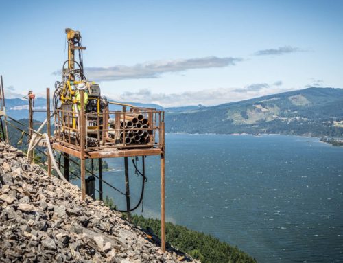
Replacement structures on steep ridgeline
Micropile Selection
Faced with the described access challenges, the owner began to explore deep foundation alternatives that could accommodate all project requirements. The solution would require compact materials and equipment that could be efficiently transported by helicopter. It would also need to accommodate low overhead clearance, as replacement foundations would be installed within the general footprint of existing foundations and the overhead lines would remain in-service throughout construction. Ultimately, the owner determined micropiles offered an efficient solution to all challenges, and specified micropile foundations for 13 steel poles.
Subsurface Challenges
The challenging location resulted in limited geotechnical information available prior to construction, and required the foundation engineer to produce initial designs from representative, non-site-specific data. This practice is fairly common in the electric transmission industry given the long linear nature of the projects. Even when access is granted or feasible ahead of construction, procuring precise geotechnical data at each foundation location would be challenging, due to the typical distance covered and sheer number of borings it would require. Baseline assumptions regarding site conditions were made from available regional geotechnical data, surficial geology reviews, and site walks. Anticipated conditions derived from this representative information are shown in Table 1 in the downloadable pdf.
The majority of the replacement structures were located on steep, narrow ridges. Data obtained during construction showed subsurface materials consisting of highly weathered basalt and intermittent layers of saprolite to depths up to 18 m below the ground surface. Saprolite is a chemically weathered rock that forms in the lower zones of soil profiles and can create major foundation complications. Saprolite encountered within the geotechnical borings was characterized as a silt, and exhibited strength and stiffness properties comparable to soils, while basalt encountered within the borings exhibited much stiffer and stronger properties as shown in Boring 11X-C1 (Figure 2). Precise identification of materials was essential to properly characterize the bond zone conditions and, ultimately, to the successful performance of the micropiles.
The relative stiffness of the geotechnical materials that micropiles bond into to develop axial resistance is of significant importance to the designer. As piles begin to transition axial load in the bond zone through grout-to-ground adhesion, the basic principles of material stiffness and load transfer need to be carefully considered. When the bond zone is composed of geotechnical materials that have significantly different stiffnesses in terms of grout-to-ground bond resistance, the pile may overstress the bond with the weaker material and transition the load to the stiffer material until it undergoes a brittle failure, leading to early failure of the pile. Given the variable bedrock profile encountered on this project, the designer had to confirm the differences in material stiffness, and utilize a bond resistance that considered both the composite stiffness and mechanical bonding characteristics of the interlayered saprolite and basalt bond zone.
Pile Design
Micropile foundations were developed to resist maximum ground line moment reactions ranging from approximately 420 to 1240 m-kN. The designs included a varying number of micropiles arranged in a circular array and connected with a steel cap.
Detailed foundation schedules were created for each site, providing foundation capacities for a range of conditions expected to be encountered. The impact of adjacent slopes, variable nature of the subsurface conditions, and limited geotechnical data available at the time of design were all taken into account. Site topography also played a major role in micropile orientation and layout. Custom lateral resistance models were developed to account for variable pile stiffness, which led to a 3D model that more accurately represented load redistribution based on overall foundation stiffness. Three, six and eight-pile layouts were developed for each site, and the design ultimately installed was determined by the foundation contractor during construction.
Steel Pile Caps
Steel caps were selected in place of concrete as they are fabricated in a controlled, offsite facility and transported to foundation locations in a single helicopter trip. Not only did this significantly reduce helicopter time associated with concrete transport, it also decreased onsite construction time. This was a major benefit to a project that experienced extreme weather on multiple occasions, and required crews to work within short and unpredictable windows.
Pile caps were designed as a single steel plate with large openings to accommodate the micropile alignment tolerances required by the contractor. Given the omnidirectional loading applied by the steel poles, finite element analysis was used to better predict bidirectional stress in the caps and stress concentrations around the openings. Utilizing finite element analysis to validate plate deflection, buckling and yielding, and welding requirements based upon principal plate stresses allowed for a significant reduction in total pile cap weight. This is critical to limiting the lifting demand placed on construction helicopters and optimizing the caps for use on projects with logistical challenges. The plates ranged from 5.7 to 9.5 cm in thickness and 147 to 193 cm in diameter.
Construction
The foundation contractor provided specialty micropile drills that could be broken into helicopter-portable components and transported to foundation sites. Leveling platforms provided stable surfaces for equipment and materials, neutralizing the steep slopes and minimizing excavation requirements in the rugged terrain. The platforms also provided a template for the rotating micropile drill, allowing for all piles in each array to be installed without relocating the drill or requiring helicopter support.
The contractor paired a patented field characterization method with the developed foundation schedules to establish the specifics of each foundation. Drilling for the first pile at each site doubled as a geotechnical test boring, which determined the quantity and length of piles, as well as cap specifications. Standard penetration testing was performed within these test borings in general accordance with ASTM D1586, where the number of hammer blows required to advance the sampler for successive 150 mm intervals is recorded, and the total number of blows required to drive the sampler from 150 to 450 mm is referred to as the SPT “N-value.” The N-value provides a general indication of in-situ soil density and consistency.
Soil samples were collected with a standard split-spoon sampler and characterized following ASTM D2488 procedures. Obtaining this data allowed the contractor to characterize the geotechnical conditions and communicate with the foundation designer to modify installation requirements as conditions changed from site to site.
Brief outages were permitted during helicopter operations to place and remove equipment, but all drilling activities took place under in-service overhead lines. The lines sat approximately 7.5 m above ground and had a Minimum Approach Distance (MAD) of 3 m, requiring the combined height of the micropile drill and platform to be less than 4.5 m. Micropile casing and all thread bar can be segmented to lengths as short as 1.5 m to assist in accommodating low MAD’s during installation.
Extreme and unpredictable weather compounded project challenges, including strong winds, rain storms, and heavy fog. To minimize schedule impacts, crews needed to be prepared to move on and off foundation sites quickly during windows of opportunity. The use of the steel pile caps allowed crews to take full advantage of these short windows. Compared to concrete caps, the steel caps reduce helicopter use by an average 74% and onsite labor time by an average 64%.
Testing + Quality Control
The foundation design team was supported by field engineers and geologists who oversaw micropile installation and testing. As previously noted, the precise identification of saprolite and basalt layers was integral to the successful performance of the foundations. The varying degree of hardness of each layer can result in difficult drilling conditions and increased stress on equipment. The saprolite zones can also produce a contracting or expanding effect in the borehole, significantly affecting borehole advancement speeds. The presence of a qualified geologist onsite allowed for the accurate identification of subsurface materials, and all piles were installed successfully.
Supplemental to onsite subsurface characterization, one micropile at each structure location was proof tested to the specified design load. Tension load testing was performed in accordance with ASTM D3689. Loads ranged from 965 to 1635 kN, and corresponding total displacements ranged from 0.58 to 1.65 cm. Proof test results confirmed approaches taken to mitigate the challenges associated with subsurface conditions and related design assumptions.
Completion
Micropiles provided a solution to the access, subsurface and other challenges this project experienced. They successfully allowed for helicopter transport to rugged sites which did not allow for conventional access, and enabled for efficient site characterization during construction, which was crucial to both foundation installation and subsequent performance. The substitution of steel pile caps also contributed to project success, allowing for significantly decreased helicopter hours and onsite labor. All foundation work was completed with no service interruptions to customers and zero safety incidents.
Lower Churchill Project
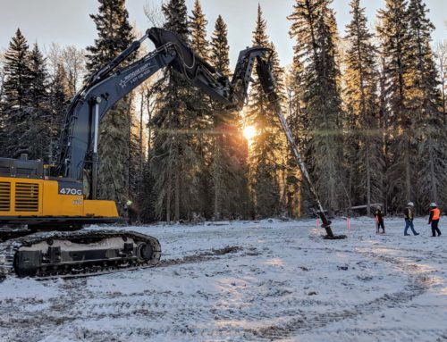
Phase I of the Lower Churchill Project in Newfoundland and Labrador, Canada provides an example of a contrasting, but similarly challenged project where micropiles played a major role in the foundation solution. The project serves to generate hydro-electric power in remote areas of Labrador and transmit it across the province, including to the island of Newfoundland. Phase I, referred to as Muskrat Falls, is over 1,100 km long and consists of approximately 1,260 self-supporting lattice and guyed structures. Boggy conditions necessitated the majority of foundation construction activities be conducted during the winter months, while the ground was frozen and ice roads could be built. During this time, temperatures ranged from highs of -13°C to lows of -40°C. Work condition challenges were compounded by average annual snowfalls of 458 cm occurring over 10 months of the year.
Subsurface Challenges
Original foundation designs included grillage and driven piles, but variable bedrock depths, fluctuating thicknesses of soft soils, and shallow groundwater created installation challenges at numerous locations. Soft, surficial soils included organic peat bogs and loose, saturated, glacially derived sands and silts, which commonly contained cobbles and boulders and generally lacked bearing support for tower foundations and side wall stability in shallow excavations.
Grillage foundations were deemed unfeasible during post-award geotechnical characterization at many locations, as they rely on a relatively shallow, dense bearing stratum that was not present. Driven piles also proved to be problematic at numerous sites after encountering shallow bedrock, commonly characterized as strong to very strong granite, gneiss, limestone/dolomite, sandstone and shales. These challenges led to early termination of piles, and foundations that could not resist the necessary structure uplift loads common to the planned lattice towers. For these locations, foundation designs would require significant embedment within soft overburden to develop adequate foundation resistance.
The ambiguity in bog depth and bedrock contact elevation, in combination with adverse site conditions for large excavation and pile driving equipment, led to numerous foundation delays during the early stages of the project. An example of typical subsurface conditions along the project alignment are shown in Figure 8.
Micropile Alternative
To aid in schedule recovery and to better handle the variable bog and bedrock conditions, micropile foundation designs were developed for sites expected to experience installation challenges. The micropiles supplemented existing driven pile and grillage designs to deliver a comprehensive solution to handle any of the following potential conditions: 1) cobbles and boulders within overburden material, 2) variable depth to bedrock between structures and within structure footprints, 3) soft overburden overlying relatively shallow hard bedrock, and 4) soft surface conditions during periods prior to freezing and during thawing.
A micropile foundation schedule was developed that considered a suite of subsurface conditions for all planned structures. Where subsurface conditions required a combination of foundation types, one-off and location-specific designs were created. These included driven pile with rock anchors and driven pile with micropiles acting as tie-down anchors for non-conforming driven pile sites. In total, micropiles were installed at 161 structures to depths up to 21 m.
Pile Design
The lattice structures installed on the project generated up to 2,100 kN of uplift, 2,650 kN of compression, and 850 kN of shear at each leg, while guyed structures generated up to 2,400 kN of compression and 292 kN of shear at the center pin. Uplift loads associated with the lattice structures required significant pile embedment to develop adequate foundation resistance.
Detailed foundation schedules were created for each site, providing foundation capacities for a range of conditions expected to be encountered. Micropile designs incorporated consideration of bog to depths up to 8 m, as well as variable quality of underlying soil and bedrock. The approach provided a flexible solution that could be efficiently adapted onsite should conditions deviate from those noted in the pre-construction site characterization, or where pre-construction test pits/borings could not be attained.
The impact of varying subsurface conditions, adfreeze conditions, and limited geotechnical data available at the time of design were all considered. In addition, site topography played a major role in micropile orientation and layout. 3D models of the various pile layouts with cap connection were developed to better evaluate load redistribution based on overall foundation stiffness.
Final micropile foundation designs consisted of three, four, six, and eight-pile configurations with maximum axial pile design loads ranging from 661 to 1216 kN. Guyed structure center pin foundations were designed with circular pile arrays, consisting of battered piles. Lattice structure foundations were designed with square layouts, consisting of both vertical and battered piles. The design ultimately installed was determined by the foundation contractor during construction based on encountered site conditions.
Structures were connected to the micropiles via steel cap. The caps were intended to accommodate multiple pile configurations to reduce the number of cap designs required. Similar to the steel pile caps used in construction of the Koolau-Wailupe project, finite element analysis was utilized. The plates ranged in thickness from 7 to 9.5 cm.
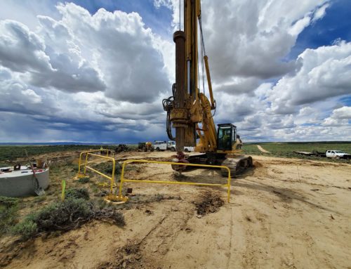
Construction
Site access in the remote, rugged terrain presented challenges to the project, and access roads were oftentimes constructed through more than 3 m of snow. During the winter months, the frozen ground provided sufficient support for equipment traveling off the access roads. During the remaining seasons, rig mats were used onsite to support equipment. The use of small, lightweight equipment common to micropile construction aided construction and access during and outside the winter months.
The same patented field characterization method and proof testing program employed on the Koolau-Wailupe project was used in conjunction with developed foundation schedules to determine the optimal design based on site-specific conditions. Additionally, foundation designs were tailored to the installing contractor’s specific equipment, tooling and capabilities, allowing for significant cost and schedule efficiencies.
Specific construction challenges included working in temperatures close to -40°C. To mitigate this, all equipment included an on-board heating system and insulation; a heated pressure washer was used to clean the drill at the end of each shift; all-thread bar and hardware required heating to above 5°C prior to installation; and insulation blankets were wrapped around the grouted piles to protect fresh grout from freezing.
Completion
Micropiles were a key component to the post-award foundation solution on Phase I of the Lower Churchill Project. Their ability to handle the unconfirmed and fluctuating subsurface conditions was a major benefit to both project schedule and constructability. The smaller materials and equipment required for construction also streamlined mobilization to a certain extent, benefitting construction operations and a project schedule that had already seen delays. In the end, the Prime Contractor successfully met their Substantial Completion date.
Summary and Implications
The helicopter portability of micropile equipment and materials provided a unique solution to previously hand-constructed sites on the steep slopes of Hawaii. In contrast, the adaptable nature of micropiles and smaller sized installation equipment provided a flexible solution to the variable depth to bedrock and ever-changing remote site conditions in Newfoundland and Labrador, Canada.
As investment in electric power infrastructure continues to expand, so too do the access and subsurface challenges facing the industry. The Koolau-Wailupe and Lower Churchill projects demonstrate the measurable impacts micropiles can have in diverse project environments faced with these challenges.
Nickolas G. Salisbury, President, Crux Subsurface Inc., Spokane, Washington USA Steven A. Davidow, P.E., S.E., Vice President, Crux Subsurface Inc., Spokane, Washington USA
References
American Association of State Highway and Transportation Officials (AASHTO) 2012, LRFD Bridge Design Specifications.
American Concrete Institute (ACI) 2008, Building Code Requirements for Structural Concrete (ACI 318- 08) and Commentary, American Concrete Institute (ACI) Committee 318, publication no. 318-08.
American Institute of Steel Construction (AISC) 2008, Steel Construction Manual, 13th edn.
American Society of Civil Engineers (ASCE) 2011, Design of Steel Transmission Pole Structures, publication no. 48-11.
American Society of Civil Engineers (ASCE) 2000, Design of Lattice Steel Transmission Structures, publication no. 10-97.
Armour, T, Groneck, P, Keeley, J & Sharma, S 2000, Micropile Design and Construction Guidelines Implementation Manual, report no. FHWA-SA-97-070.
Armour, T, Groneck, P, Keeley, J, Sabatini, PJ, Tanyu, B 2005, Micropile Design and Construction Reference Manual, report no. FHWA-NHI-05-039.
Autodesk Inventor Professional. Computer software. Http://usa.autodesk.com/autodesk-inventor. Vers. 2015. Autodesk.
Georgiadis, K., and Georgiadis, M.. "Undrained Lateral Pile Response in Sloping Ground." Journal of Geotechnical and Geoenvironmental Engineering 136.11 (2010): 1489.
GROUP. Computer software. Http://www.ensoftinc.com/. Vers. 14. Ensoft, Inc.
Post-Tensioning Institute (PTI) 2004, Recommendations for Prestressed Rock and Soil Anchors, ISBN 1- 931085-29-3.
Reese, L. C., and Van Impe, W. F. (2001). Single Piles and Pile Groups Under Lateral Loading. A. A. Balkema, Rotterdam, Netherlands. 463 pgs.
Wyllie, Duncan C 1999, Foundations on Rock, E & FN Spon, London. 310-313.
American Concrete Institute (ACI) 2008, Building Code Requirements for Structural Concrete (ACI 318- 08) and Commentary, American Concrete Institute (ACI) Committee 318, publication no. 318-08.
Crowther, G. Scott. "Frozen Soil Strength Criteria for Lateral Pile Analysis." Journal of Cold Regions