Challenges faced in foundation design and construction are nothing new to electrical infrastructure projects. With power demands steadily increasing, utilities are building, upgrading and/or replacing assets at a remarkable rate. These projects increasingly require construction through areas with limited access, environmental constraints and unknown geotechnical conditions, necessitating innovative design and construction techniques.

Project Details
The substations serving the Hawaii Kai area on the island of Oahu are powered by two 46 kV circuits: Koolau-Wailupe No. 1 and No. 2. After experiencing multiple outages due to high winds, the owner, Hawaiian Electric Company (HECO), commissioned an upgrade of these circuits, involving the replacement of several wooden structures with self-supporting steel poles.
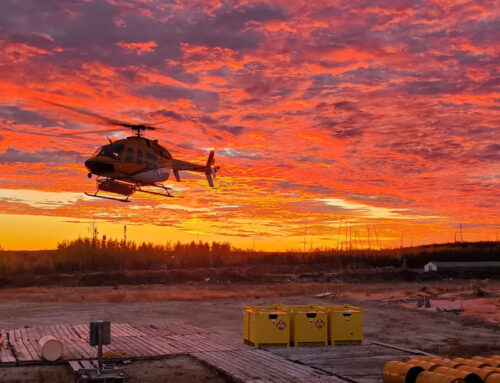
Although the linear distance between the community and substations is not significant, it is populated with rugged mountainous terrain, and the structures requiring replacement were located on remote, steep slopes. Additional challenges faced on this project included unpredictable weather and working under existing lines, which were to remain energized throughout construction. Road development was not feasible, and it was determined that at least nine structures would require construction using only helicopter-assisted methods.
Micropile Selection
Faced with these access challenges, the owner began to explore deep foundation alternatives that could accommodate all of the project requirements. The solution would require compact equipment and materials that could be transported efficiently by a light or medium lift helicopter. The equipment would also need to accommodate low overhead clearance to allow the new foundations to be constructed within the general footprint of the existing foundations, and to enable the existing energized lines to remain in-service throughout construction. Ultimately, the owner determined that micropiles offered an efficient solution to the identified challenges, and specified micropile foundations for 13 tubular steel poles.
Subsurface Challenges
Only limited geotechnical data was available prior to construction, which required the foundation designer, Quanta Subsurface, to produce initial or preliminary designs based on representative and non-site-specific data. Baseline assumptions of the onsite conditions were made based on available regional geotechnical data, surficial geology reviews and site walks.
This practice is fairly common in the electric transmission and distribution industry given the long, linear nature of the projects. Procuring precise geotechnical data at each foundation location is challenging given the typical area covered and number of geotechnical borings this would require. This is especially true for projects featuring any sort of logistical restriction, as access is often only granted at the time of construction.
The majority of the replacement structures on the Koolau- Wailupe circuits were located on steep, narrow ridges. Data obtained during construction indicated that the subsurface materials comprised highly-weathered basalt and intermittent layers of saprolite to depths up to 60 ft (18.3 m) below the ground surface. Saprolite is a chemically weathered rock that forms in the lower zones of soil profiles and can create major foundation complications. Saprolite encountered within the geotechnical borings was characterized as a silt (MH) and exhibited strength and stiffness properties comparable to soils, while the basalt that was encountered within the borings exhibited much stiffer and stronger properties (Boring 11X-C1). The transition zone rock, often referred to as saprock, exists where the behavior of the subsurface material changes from soil to rock. Precise identification of the materials was essential to properly characterize the conditions in the bond zone and, ultimately, to the successful performance of the installed micropile.
The relative stiffness of the geotechnical materials that micropiles bond into to develop axial resistance is of significant importance to the designer. As piles begin to transition or transfer the axial load in the bond zone through the grout-to-ground adhesion, the basic principles of material stiffness and load transfer need to be carefully considered. When the bond zone is composed of geotechnical materials that have significantly different stiffness in terms of grout-to-ground bond resistance, the pile may overstress the bond with the weaker material and transition the load to the stiffer material until it undergoes a brittle failure, leading to early failure of the pile. Given the variable bedrock profile encountered on this project, the designer had to recognize the differences in material stiffness and utilize a bond resistance that considered both the composite stiffness and mechanical bonding characteristics of the interlayered saprolite and basalt bond zone.
Pile Design
Micropile foundations were selected and developed to resist the maximum moment reactions at the ground line, which ranged from approximately 3,700 to 11,000 in-kips (418 to 1,243 kN-m). The designs included a variable number of micropiles arranged in a circular array and connected together with a steel pile cap.
Detailed foundation schedules were created for each site, providing the capacities of the micropile foundations for a range of conditions that were expected to be encountered. The impact of the adjacent slopes, variable nature of the subsurface conditions and limited geotechnical data available at the time of design were all considered during the process. Site topography also played a major role in micropile orientation and layout. Custom numerical models of lateral resistance were developed to account for variable pile stiffness, which led to a 3D model that more accurately represented the load redistribution based on the overall foundation stiffness. Ultimately, designs incorporating three, six or eight micropiles were developed for each site. The exact design installed was determined by the foundation contractor during construction.
Steel Pile Caps
Steel caps were selected in lieu of concrete as the steel caps can be fabricated in a controlled, offsite facility and transported to foundation locations in one helicopter trip. Not only did this choice significantly reduce helicopter time that would have been associated with the concrete transport, but it also decreased the onsite construction time. The use of the steel caps provided a major benefit to a project, which experienced extreme and unpredictable weather on multiple occasions, requiring crews to perform their activities within short and unpredictable work windows.
The steel pile caps were designed as a single steel plate with large openings to accommodate the micropile alignment tolerances required by the contractor. Given the omnidirectional loading applied by the steel poles, finite element analysis was used to better predict the development of bidirectional stresses in the caps and the stress concentrations around the openings. Ultimately, the plates ranged from 58 to 76 in (1,473 to 1,930 mm) in diameter and 2.25 to 3.75 in (57 to 95 mm) in thickness.
The development and implementation of lightweight steel micropile caps used in the electric transmission industry has been precipitated through the use of advanced finite element analysis. Utilizing these techniques to validate plate deflection, buckling and yielding, and to determine welding requirements based upon principal stresses in the plate, allows for a significant reduction in the total weight of the pile cap. The reduction in weight is critical to limiting the lifting demand placed on construction helicopters and to optimizing the steel caps for use on projects with logistical challenges.
Construction
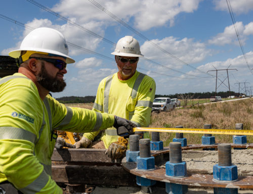
The foundation contractor, Crux Subsurface, provided the specialty micropile drills that could be disassembled into helicopter-portable components and transported to the foundation sites. Leveling platforms provided stable surfaces for the equipment and materials, neutralizing the steep slopes and minimizing excavation requirements in the rugged terrain. The platforms also provided a template for the rotating micropile drill, allowing for all piles in each array to be installed without relocating the drill or without requiring support from the helicopter.
The foundation contractor paired a patented field characterization method with the developed foundation schedules to establish the specifics for each foundation. Drilling the first pile at each site also doubled as a geotechnical boring, which determined the quantity and length of piles in addition to the specifications for the steel cap for that micropile foundation. Standard penetration testing (SPT) was performed within these test borings in general accordance with ASTM D1586, Standard Test Method for Standard Penetration Test (SPT) and Split-Barrel Sampling of Soils.
The number of hammer blows required to advance the sampler for successive 6 in (152 mm) intervals is recorded, and the total number of blows required to drive the sampler from 6 to 18 in (152 to 457 mm) is referred to as the SPT N-value. The N-value provides a general indication of in-situ soil density and consistency. Soil samples were collected with a standard split-spoon sampler and characterized following ASTM D2488 procedures, Standard Practice for Description and Identification of Soils (Visual-Manual Procedures).
Obtaining this subsurface data allowed the contractor to characterize the geotechnical conditions and to communicate with the foundation designer when modifications were required to the installation requirements, as conditions changed from site to site. The potential for an increase or decrease in the length and quantity of the micropiles necessitated an adaptable pile cap design that could satisfy a variety of conditions.
Brief outages were permitted during helicopter operations required to place and remove equipment and materials, but all drilling activities occurred under in-service energized overhead lines. The height to the overhead lines were approximately 25 ft (7.6 m) above ground and had a Minimum Approach Distance (MAD) of 10 ft (3.05 m), requiring the combined height of the micropile drill and platform to be less than 15 ft (4.6 m). The micropile casing and all-thread bar was segmented to lengths as short as 5 ft (1.5 m) to assist in accommodating the low MAD during installation.
Extreme and unpredictable weather compounded project challenges, including strong winds, rain storms and heavy fog. To minimize schedule impacts, crews needed to be prepared to move on and off the foundation sites as quickly as possible during the small windows of opportunity. As previously mentioned, the use of the steel pile caps allowed the crews to take full advantage of these small windows. Compared to concrete caps, the steel caps reduced helicopter usage by an average of about 74% and the onsite labor time by an average of about 64%.
Testing and Quality Control
The foundation design team was supported by field engineers and geologists who oversaw the installation and testing of the micropiles. As described, the precise identification of saprolite and transition zones was integral to the successful performance of the foundations. The varying degree of hardness of each layer can result in difficult drilling conditions and increased stress on the equipment. The saprolite zones can also produce a contracting or expanding effect in the borehole, significantly affecting borehole advancement speeds. The presence of a qualified geologist onsite allowed accurate identification of the subsurface materials, and all of the piles were installed successfully.
Supplemental to onsite subsurface characterization, one micropile at each structure location was proof tested to the specified design load. Tension load testing was performed in accordance with ASTM D3689, Standard Test Methods for Deep Foundations Under Static Axial Tensile Load. The tension loads ranged from 217 to 368 kips (965 to 1,637 kN), and corresponding total displacements ranged from 0.23 to 0.65 in(5.8 to 16.5 mm). The results of the proof tests confirmed the approaches taken to mitigate the challenges associated with the challenging subsurface conditions and related design assumptions were accurate and effective.
Summary
Linear transmission and distribution projects pose unique challenges for foundation contractors. Transmitting power from generation to end users often necessitates crossing unique terrain, sometimes involving significant access limitations, regional material availability and a lack of site-specific geotechnical data. The islands of Hawaii compounded these challenges in this particular case, incorporating unique wind zones, dense forested areas and extremely rugged mountainous terrain. These challenges created the opportunity for a foundation design and construction approach able to adapt to the restrictive site conditions, variable subsurface environments and limited site-specific information available prior to design.
The Koolau-Wailupe circuits join a long list of electrical infrastructure projects to have benefitted from the use of micropile technology in recent years. The compact equipment and materials used to install the foundations allowed for alternative access methods when road construction was not an option. The compact equipment also enabled construction under in-service lines, which is not an unusual requirement on line upgrade projects. The ability to characterize site-specific subsurface conditions at the time of construction and efficiently adjust the foundation designs to match the conditions encountered was a major advantage on a project that did not allow for a comprehensive preconstruction geotechnical investigation. Finally, the installation of lightweight, prefabricated steel pile caps resulted in significant benefits to the schedule and safety on this challenging project.
With significant investment in electric infrastructure expected to continue and renewable initiatives pushing this infrastructure into more remote areas, similar foundation design and construction challenges will most certainly remain prevalent. Micropiles and other alternative foundation types are providing viable solutions to these challenges, promoting growth and development throughout the deep foundation industry.