Micropiles in Harsh Northern Climates
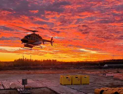
Foundation construction in subfreezing temperatures is a challenge in and of itself. The logistics of mobilizing large equipment and maintaining safe, efficient operations requires planning, experience and heightened attention to detail. However, combine this with highly-variable subsurface conditions, and the challenges multiply quickly. These were the conditions facing team members on the Labrador- Island Link project, which consisted of over 600 mi (966 km) of new transmission line in Newfoundland and Labrador, Canada. Challenges associated with grillage and driven pile installation ultimately led to micropiles being introduced as a supplemental foundation type along the alignment.

Micropile installation in frozen ground.
The Project
The Lower Churchill Project is intended to develop the hydroelectric potential of the Churchill River, which is located in Eastern Canada and is one of the most attractive hydroelectric resources in North America. With current capacities of 5,428 MW and planned projects that will significantly add to this, it’s among the largest hydroelectric power generators in the world.
Phase I of the project includes construction of the Labrador-Island Link, a new 683 mi (1,100 km) long high-voltage transmission line carrying power generated at Muskrat Falls in Labrador to Soldiers Pond on the island of Newfoundland. The work consists of 3,223 guyed and selfsupporting towers that were planned to be installed across the alignment on a combination of grillage and driven piles.
Installation Challenges
Prefabricated or componentized foundation types were specifically chosen for this harsh environment over more conventional foundation options utilizing cast-in-place concrete. Material availability and temperature control in this remote area of Northern Canada posed significant challenges to sites where concrete would be placed. Shallow grillage and driven pile foundations initially solved this geographic challenge but variable bedrock depths, fluctuating thicknesses of soft soils and shallow groundwater created additional obstacles at numerous sites. Soft, surficial soils included organic peat bogs and loose, saturated, glacially-derived sands and silts, which commonly contained cobbles and boulders and generally lacked bearing support for tower foundations and side wall stability in shallow excavations.
Grillage foundations were deemed infeasible during post-award geotechnical characterization at many locations, as they rely on a relatively shallow, dense bearing stratum. Driven piles also proved to be problematic at several sites after encountering shallow bedrock, commonly characterized as strong-to-very strong granite, gneiss, limestone/dolomite, sandstone and shales. Cobbles and boulders also posed challenges to driven pile construction. These challenges led to the early termination of piles and to foundations that could not resist the structure’s uplift loads for the selected towers.
The ambiguity in bog depth and bedrock contact elevation, in combination with adverse site conditions for large excavations and pile driving equipment, led to numerous foundation delays during the early stages of the project. While foundation retrofits were possible at some of the problematic sites, several of the installations required an alternate solution that had not been previously contemplated. The project team began to explore alternative options for these sites.
Alternative Considerations
The selected alternative(s) would need to supplement grillage and driven pile foundations in accommodating a wide range of conditions, which included:
- Cobbles and boulders within the overburden material
- Variable depth to bedrock between structures and within a structure’s footprint
- Soft overburden overlying relatively shallow hard bedrock
- Soft surface conditions during periods prior to freezing and during thawing
The foundations would also need to meet the necessary capacity requirements. Planned lattice structures for the project would generate up to 472 kips (2,100 kN) of uplift, 595 kips (2,650 kN) of compression and 190 kips (850 kN) of shear at each leg. Guyed structures would generate up to 540 kips (2,400 kN) of compression and 65 kips (292 kN) of shear at the center pin. Uplift loads associated with the lattice structures would require significant pile embedment to develop adequate foundation resistance. Accessibility was not a driving factor behind alternative foundation selection but was certainly a consideration. Access roads were constructed along the length of the alignment, which came close to each structure location but did not provide direct access to each footing/foundation site. In the winter months, the frozen ground provided sufficient support for most materials and equipment to traverse this distance of approximately 50 to 100 ft (15 to 30 m). In the summer months, with boggy and wet conditions, matting was required to bridge the gap.
Micropile Integration
Ultimately, it was determined that micropiles, in combination with drilled pipe piles and the existing grillage and driven piles, would provide the optimal solution. Micropiles can be readily adapted onsite to accommodate a range of conditions, which was crucial to the success of this project. In addition, the equipment and materials required for installation can be relatively small and lightweight while still achieving high capacities.
Detailed micropyle foundation schedules were created for each site, providing foundation capacities for a range of expected conditions. Where subsurface conditions required a combination of foundation types, one-off and location specific designs were created, which included driven pile with rock anchors and driven pile with micropiles acting as tiedown anchors for nonconforming driven pile sites.
Micropile designs incorporated potential bog to depths up to 25 ft (8 m), variable quality of underlying soil and bedrock, adfreeze conditions and the fact that limited geotechnical data was available at the time of design. The approach provided a flexible solution that could be efficiently adapted onsite should conditions deviate from those noted in the preconstruction site characterization or where preconstruction test borings could not be attained. Site topography also played a major role in micropile orientation and layout. 3D models of the various pile layouts with cap connections were developed to better evaluate load redistribution based on overall foundation stiffness. Finally, foundation designs were tailored to the installing contractor’s specific equipment, tooling and capabilities, allowing for cost and schedule efficiencies.
Final Designs
Micropile designs consisted of three-, four-, six- and eight-pile configurations, with maximum axial pile design loads ranging from 148 to 273 kips (661 to 1,216 kN). Guyed structure center pin foundations were designed with circular pile arrays, consisting of battered piles. Lattice structure foundations were designed with square layouts, consisting of both vertical and battered piles. The design ultimately installed at each site was determined by the foundation contractor during construction based on encountered conditions.
Structures were connected to the micropiles via steel caps, which were designed to accommodate multiple pile configurations to reduce the number of cap variations required. Finite element analysis (FEA) was used to better predict bidirectional stress in the caps and stress concentrations around the openings. Utilizing FEA to validate plate deflection, buckling and yielding and welding requirements based upon principal plate stresses allowed for a significant reduction in total pile cap size and weight, which is highly beneficial to projects with access and other logistical challenges. The plates ranged in thickness from 2.75 to 3.75 in (7 to 9.5 cm).
Construction
In total, micropiles were installed at 161 structures to depths up to 70 ft (21 m). The contractor paired a patented field characterization method with the developed foundation schedules to establish the specifics of each foundation. Drilling for the first pile at each site doubled as a geotechnical test boring, which determined pile quantity and length, as well as cap specifications. Standard penetration testing (SPT) was performed within these test borings in general accordance with ASTM D1586, where the number of hammer blows required to advance the sampler for successive 6 in (15 cm) intervals is recorded, and the total number of blows required to drive the sampler from 6 to 18 in (15 to 45 cm) is referred to as the SPT N-value. The N-value provides a general indication of in-situ soil density and consistency.
Specific construction challenges included working in winter temperatures close to -40°F (-40°C). To mitigate this, all equipment included an on-board heating system and insulation, a heated pressure washer was used to clean the drill at the end of each shift, all-thread bar and hardware required heating to above 41°F (5°C) prior to installation, and insulation blankets were wrapped around grouted piles to protect the fresh grout from freezing. When dust control was not possible due to low temperatures, the project team implemented a respirator fit test and management program. To decrease safety concerns, crews were equipped with climate-appropriate, nonslip footwear and hand wear, and encouraged to take regular breaks in warm vehicles. In addition, lighting was installed on all equipment to accommodate the short daylight hours during winter months.
The relatively compact and lightweight nature of micropile materials and installation equipment was beneficial to logistical concerns in all seasons. The smaller items were sufficiently supported on frozen ground in the winter and required significantly less matting than other foundation types in the wet/boggy spring and summer conditions. Size was also a factor when maintenance issues arose, which were common given the climate. Long, linear projects like this one mean that foundation sites are often a significant distance from staging yards and other project amenities. The logistics of transporting large pieces of equipment for service and repairs can be much more complicated than smaller pieces.
Testing and Quality Control
The foundation design team was supported by field engineers and geologists who oversaw micropile installation and testing. One micropile at each structure location was proof tested to the specified design load. Tension load testing was performed in accordance with ASTM D3689. Loads ranged from 201 to 368 kips (965 to 1,635 kN) and Completion On a project that was already facing substantial weather and logistical challenges, micropiles provided a key component to ensuring successful foundation construction. Their ability to handle the unconfirmed and fluctuating subsurface conditions was a major benefit to the corresponding total displacements ranged from 0.22 to 0.65 in (0.58 to 1.65 cm). The results from the proof tests confirmed that the approaches taken to mitigate subsurface challenges and related design assumptions were successful.
Completion
On a project that was already facing substantial weather and logistical challenges, micropiles provided a key component to ensuring successful foundation construction. Their ability to handle the unconfirmed and fluctuating subsurface conditions was a major benefit to both constructability and a schedule that had seen delays. All foundations were successfully installed, the prime contractor met its substantial completion date, and the Labrador-Island Transmission Link was energized in 2018.
As power sources continue to be developed in more remote areas, an increasing number of transmission projects are facing these logistical and engineering challenges. Project conditions are restricting equipment types and construction methods, and foundations that were once considered uncommon to the industry are becoming more and more prevalent.