Abstract
The following text will present the concept of rock socketed drilled shafts used to support electrical substation structures, and discuss the cost and schedule risks that traditional design responses to unforeseen shallow rock can pose to a project. Design considerations will be detailed, including rock characterization, shear strength of drilled shafts, and modeling lateral resistance of the shaft and surrounding rock. The specific case of drilled shafts installed for heavily loaded structures at the Moxie Freedom Substation will provide an example of how close collaboration between the engineer and contractor to refine designs based on site-specific feedback can provide tangible benefits to the project. In this example, value engineered designs resulted in an approximate 40% reduction in shaft/concrete volume and a 60% reduction in total rock socket depth.

Authors:
Steve Davidow, P.E., S.E., Senior Vice President, Quanta Subsurface, Spokane, WA, United States, 509.789.7787, [email protected]
Brock Wallis, Vice President, MJE Drilling, Iron Mountain, MI, United States, 906.776.4450 – [email protected]
Project Overview
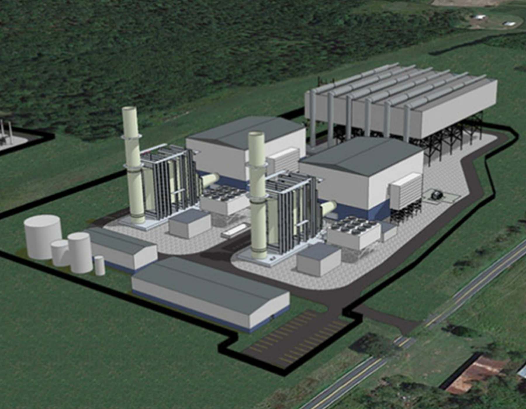
The Moxie Freedom Project included the construction of a new 500 kV switchyard in Berwick, Pennsylvania. The foundation contractor was selected to install both small and large diameter drilled shaft foundations to support the structures within the switchyard. The small diameter shafts were utilized to support transformers, switches, bus supports and a static mast, while the large diameter shafts were used to support one 180-foot monopole and six H-Frame structures.
Challenges: Rock Socketed Drilled Shafts
Available geotechnical data at the time of bid included limited borings and seismic refraction. The borings were not located at every structure, and the contractor and design engineer were left to interpret desktop studies and geophysics to determine the probable site-specific conditions at each foundation. The data suggested substantial variability in the quality and depth to bedrock across the project area, indicating significant risk of deep embedment into bedrock at all seven large diameter shaft locations.
Rock socketed drilled shafts pose unique challenges for both designers and contractors, and the topic has become a focus of national foundation organizations. Traditional design models result in deeper and/or larger diameter shafts where rock is encountered. In the case where site-specific geotechnical conditions are not clearly understood and rock is encountered at shallow depths, this can lead to significant additional rock drilling, impacting overall project cost and schedule. Rock drilling can result in more than ten times the cost of soil drilling and can easily take in excess of ten times longer to excavate.
In many situations, rock exists under a stratum of overburden of sufficient thickness compared to the pile length. In such cases, the computed deflection of the pile at the rock interface is so small that the resistance of the rock is insignificant, and the response of the pile minimal, regardless of the stiffness of the rock. In contrast, drilled shafts are used in situations where the rock contact is near or at the ground surface, imparting a significant amount of lateral demand and deflection into the rock mass. In these cases, particularly where axial loads are low and lateral loads are high, as in electrical structures, lateral loading will dictate the design rock penetration length. It has been customary in the industry to apply the same techniques developed for laterally-loaded piles in soil to laterally-loaded rock socketed drilled shafts, which can yield conservative results and often leads to excessive socket length.
Key variables in defining the demand on the drilled shaft, and proportioning the shaft reinforcing and length, include assumed depth to rock, rock mass stiffness, and concrete shear strength. In many cases, electrical structures are specified in locations with no site-specific borings and therefore no actual measurement of rock contact elevation or rock strength. Minimum shaft lengths and minimum socket lengths into rock are typically defined by the designer based on assumptions regarding site-specific geotechnical conditions. Drilled shafts socketed into rock see a significant amount of peak shear at the rock interface as a result of common methods of foundation evaluation. The minimum depth of embedment into rock is an iterative evaluation of internal stress due to lateral bearing on the rock and the assumed concrete shear capacity.
In cases where the rock contact surface is encountered shallower than anticipated, the designer and contractor must consider the value of shortening the shaft length, modifying the reinforcing cage, and eliminating some of the rock excavation. The designer must also evaluate the capacity of the rock mass to develop the assumed lateral resistance illustrated by the design method used. The rock mass may be assumed to be homogeneous in nature, when in fact has highly weathered and fractured rock over a more intact rock mass. These conditions can often be identified through the drill action during construction. Small changes in assumed rock quality can yield significant differences in peak shear forces in the shaft design models.
With a spike in peak shear demand for shallow rock socketed drilled shafts, the designer is typically left with three options to mitigate the excessive shear force; increase shaft diameter, increase shaft length, or add shear reinforcing. Typically, a combination of these results in the optimal solution. The designer can also review the assumed concrete shear strength using either American Concrete Institute (ACI) simplified or detailed design methods; based upon the final shaft geometry, reinforcing ratio, and internal forces.
Original Design Review
MJE Drilling (MJD), the foundation contractor, engaged Quanta Subsurface (QS), the design engineer, to review available geotechnical data and structure loading, and to determine if an alternate shaft design could be employed if shallow rock was encountered. Of key importance was the determination of rock risk to the installations, and the development of mitigation options to deal with unforeseen subsurface conditions.
Substation buildouts consist primarily of an assembly of smaller components and switch gear, which are supported by relatively small foundations. Larger structures, such as H- or A-frames and self-supporting dead-end poles or towers, are required where the transmission line enters and exits the substation. These structures develop much larger foundation reactions. The focus of the geotechnical and foundation review for this project was on three H-Frame structures and one self-supporting dead-end pole.
A desktop study revealed that regional topography in the project area ranges from broad low relief alluvial terraces and rolling hills with incut streams and river valleys, to high relief elongated ridges separated by narrow valleys. The overburden soils generally consist of Olean Till. The bedrock underlying the project site is mapped as alternating beds of olive gray siltstone, mudstone, and sandstone, with red siltstone, mudstone, and shale. Initially, seven borings were provided within the substation footprint, with seismic refraction provided between the borings as shown in Fig. 1. None of the borings were located directly at the four structures under consideration, leaving the designer and contractor to make interpretations on the actual depth to rock and quality of rock at each location. The use of geophysics, such as seismic refraction, can be a very useful tool for designers and contractors in situations where precise geological data cannot be obtained at a foundation site. The borings shown in Fig. 1 were used to calibrate the seismic refraction data obtained from the field, and estimate the probable depth to rock. Like any estimate, the interpretation of this data is subjective and poses a risk of changing conditions to the contractor. It is important to note that in electrical transmission and substation design, as opposed to transportation or commercial structure projects, the foundation designer is often left to design with representative geotechnical information and not site-specific borings. Interpretation of representative borings, geophysics, and desktop geotechnical studies create subjective approaches to modeling that should be revisited throughout construction as actual site conditions may differ.
As shown in Table 1, the H-frame structures had relatively moderate to low loading but a high risk of shallow bedrock, based upon the borings and geophysics provided by the owner. Drilling at adjacent foundations identified that the bedrock strata mapped by geophysics was variable. The dead-end pole reaction was fairly high and required a significant minimum embedment into rock to minimize the shear demand on the shaft.
As shown in Table 1, the H-frame structures had relatively moderate to low loading but a high risk of shallow bedrock, based upon the borings and geophysics provided by the owner. Drilling at adjacent foundations identified that the bedrock strata mapped by geophysics was variable. The dead-end pole reaction was fairly high and required a significant minimum embedment into rock to minimize the shear demand on the shaft.
Design Optimization
QS coordinated closely with MJD to compare the available tooling on or near the project location to the tooling required for proposed shaft designs, and to quantify the impact on the drilled shaft designs should rock be encountered shallower than expected. From this set of criteria, alternate drilled shaft designs were developed and potential impacts to project cost and schedule were analyzed. These designs incorporated detailed geotechnical assessments and constructability reviews derived from continuous interaction between project team members. As previously described, a review of site-specific rock modeling results and code provisions for shear design of concrete shafts was conducted to better characterize the issues and solutions surrounding rock socketed drilled shafts.
During initial drilling operations for the dead-end pole, weathered sandstone was encountered at a depth of 17 feet. The rock mass was fairly weak to a depth of 27 feet, and particularly weathered in the upper 3 to 5 feet of the rock contact. This was based on initial boring data and observations made by QS field geotechnical and geology groups. Close interaction between the contractor and the field engineering staff is critical to determining if and when technical adjustments in modeling and approach are necessary. Initial shaft modeling using both LPile and MFAD had assumed fairly strong, uniform rock, which developed a tremendous peak shear demand on the shaft at the rock contact surface. By reviewing the lateral earth pressure generated by the peak shear at this upper rock contact surface in combination with the observed drill resistance during the excavation of the rock, it was determined that the physical demand of the shaft lateral bearing against the observed rock mass was not correct in the initial models. By accounting for the site-specific rock quality observed during construction and modeling the p-y rock response of the upper rock surface as a weaker, more weathered material, the peak shear demand was reduced, and a smoother shear distribution was developed.
The initial approach looked at concrete shear using the ACI simplified shear equations (shown in Table 2), which is standard and conservative for most concrete shear analyses. In this case, where shear is critical and the combinations of applied loads are somewhat unique, a more detailed assessment of shear strength can be helpful. By considering the amount of reinforcing utilized in the preliminary design, and acknowledging the amount of shear and moment that occur simultaneously in the critical section of the shaft, a 75% increase in shear strength can be recognized.
By employing a combination of revised rock modulus and strength parameters in combination with more detailed shear strength provisions within ACI, the rock socket lengths, and in some cases the shaft diameters, were reduced.
Value Engineering Results
Final designs, and those ultimately approved by the facility owner, resulted in an approximate 40% reduction in shaft/concrete volume and a 60% reduction in total rock socket depth. The drilled shaft supporting the 180-foot monopole was redesigned as an 11-foot-diameter, 25-foot-long shaft with a minimum shaft embedment into rock of 7 feet. The results of the analysis are shown in Table 3.
The assumptions made in rock quality and strength play a critical role in the development of peak shear demand in rock socketed drilled shafts. The designer must decide if the rock mass should be modeled as a homogeneous unit or broken out into layers to better represent the weathering and strength properties at the site. Once the initial analysis is complete, the designer must determine if the rock mass can support the lateral loading defined by the modeling. In this case, feedback from field operations determined that the upper five feet of the rock mass was not capable of supporting the peak shear loads developed in the original model, and a revised lateral resistance model was created. Unique rock resistance models were created for each foundation site during drilling operations by generating modified p-y curves representing the variable rock quality at each site. These new models recognized the more significant weathering and reduced rock quality identified during site activities. The structural engineers also utilized the detailed shear modeling to determine if an increased concrete shear capacity would benefit the shaft construction. Both of these design refinements were instituted in an iterative process to converge on an optimal solution.
Utilizing the same construction approach described previously, the reduction in concrete volume and rock socket depth reduced construction schedules by two weeks, and eliminated the need for extended work hours and additional crew support. A combination of better rock mass characterization during drilling operations and recognition of higher concrete strength values provided the opportunity to significantly reduce the rock excavation volumes and total concrete required on the project. Table 4 provides a more detailed comparison of foundation construction between the preliminary and final designs.
Summary and Conclusion
Rock socketed drilled shafts continue to challenge designers and contractors alike, particularly where high lateral loads and flexure are applied. Current modeling techniques conservatively predict very high peak shear demand in shallow rock conditions, requiring the designer to generate large shaft designs with significant rock excavation. To achieve optimal design and construction results, the contractor and designer should work in tandem to define the actual site conditions during construction, and be prepared to adapt the modeling and approach to site-specific feedback.
As the Moxie Freedom Substation heavy load structure foundations were initially excavated, constant interaction between the design engineer’s field geotechnical staff, the foundation designers, and the subsurface contractor, created a more accurate view of the subsurface resistance. This created the opportunity to refine conservative initial modeling based upon limited data, generate foundation solutions that matched the site conditions, and create significant value for the customer.
Reference List
ACI Committee 318. 318-14: Building Code Requirements for Structural Concrete and Commentary. American Concrete Institute, 2014, 318-14: Building Code Requirements for Structural Concrete and Commentary.
ACI Committee 336. 336.3R-14 Report on Design and Construction of Drilled Piers. American Concrete Institute, 2014, 336.3R-14 Report on Design and Construction of Drilled Piers.
Benz, Evan C., and Michael P. Collins. “Updating the ACI Shear Design Provisions.” Concrete International, vol. 39, no. 9, 9 Jan. 2017, pp. 33–38.


