Horizontal Geotechnical Investigations for Tunneling
Introduction
Geotechnical investigations for tunneling projects typically use vertical test borings and, to a lesser extent, angled borings. Horizontal drilling applications were often limited to specialty testing programs and to perform probe drilling from a tunnel boring machine (TBM) as part of production tunneling. The former often involved cumbersome setups with skid rigs and cribbing in a pilot tunnel or shaft. The latter usually was limited to generic probing for rock quality and ground water conditions with no sampling. Neither yielded continuous core at production rates suitable for design and construction planning.
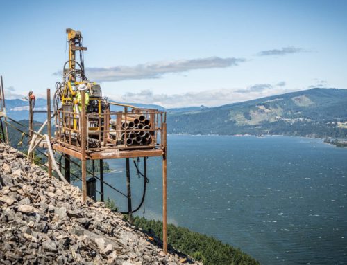
Conventional vertical investigations still make sense in many instances, particularly for tunnels planned beneath urban settings where truck access is convenient and where the tunnel horizon is not readily accessible via a portal or shaft. However, equipment is presently available to conduct horizontal geotechnical investigations at reasonable production rates and cost. Advantages include continuously sampling the tunneling horizon and minimizing “access drilling” to get the zone of interest at the underground construction horizon. Horizontal boring lengths of up to approximately 800 m are considered feasible and those in the range of 150 to 300 m are now routine.
These capabilities make horizontal borings an attractive option to consider when looking at deep tunnels beneath ridges, especially where access is limited. Fewer drilling staging sites can also mean reduced environmental impacts when investigating tunnels proposed beneath sensitive lands such as public wilderness areas. Investment in early construction packages to develop portals for investigation access and, possibly in excavating test shafts for the same purpose should even be considered.
Potential benefits in the form of achieving improved overall project costs using horizontal borings exist because of the significant additional data collected in the tunnel horizon. For this reason they should be considered during the routine cost-benefit analyses generally conducted for planning geotechnical investigations for tunneling. The authors also believe that collection of such data will reduce Geotechnical Baseline Report (GBR) conservatism and lead to lower potential for construction claims for differing site conditions. Additional applications during construction can also lead to improved tunneling efficiency and the viability of contractor implementation of value engineering alternatives.
This paper is intended to provide an overview of applicable concepts and technologies involved in executing horizontal borings for tunneling; highlighting both benefits and potential shortcomings or areas of future development needed to achieve more widespread application. Several case histories are presented to emphasize the concepts, technologies, benefits and different types of applications possible.

Horizontal drill rig set up in bottom of Las Vegas Wash Tunnel shaft
Concepts and Technologies
General
Successfully performing horizontal borings for tunneling requires specialty equipment and expertise. When accomplished, one produces not only a continuous geotechnical sample within the tunnel, but also a small diameter “pilot tunnel”. But in order to include such investigations in a tunnel planning or design program they have to be cost effective. This assessment can be based on a variety of perceptions of value depending upon geologic factors, contractual mechanisms, risk management environment, and likely tunneling technology, including the perceived need for ground modification. Cost and limitations need to be evaluated relative to those of conventional borings. Future developments should continue to reduce cost and eliminate some current limitations.
Specialty Equipment
Key features associated with the drilling rigs include enhanced survey, navigation, and depth capabilities. Recent developments have included development of an automated “wrenchless” operating system whereby wireline rod strings are tripped in and out of the borehole without rigorous operator handling. For the types of rigs being developed for horizontal drilling, typical access requirements are relatively level work platforms at portals that are approximately 5 m wide by 8 m long or access shafts approximately 5 m in diameter.
Special considerations regarding drill steel and bits as well as drilling control are also important. Specialty drill string considerations include full hole core barrels, drill rod stabilizers, and non-abrasive reamers. During drilling, as with most rotary drilling, maintaining controlled, continuous fluid at the bit is critical to recovery, bit wear and borehole stability. Avoiding or dealing with lost circulation in a horizontal hole can involve additional steps and precautions such as special fluid retention devices installed in the core barrels. These devices maintain preset fluid pressure in the rod string by limiting the flow of fluid past the bit. Clearly, additional thought and care are advised when there is risk of losing drilling tools that could become a continuous obstruction in the tunneling horizon.
Because of the effects of gravity and rotation, horizontal borings tend to deviate as much or more than vertical borings and require deviation surveys to monitor deflection and allow for possible corrections. Horizontal borings in general tend to deflect differentially depending on the hardness of the rock or soil. Geologic factors such as bedding and jointing can also affect borehole deviation. Hence, deviation surveys are routinely performed by single or multi-shot magnetic or optical survey tools. Non-magnetic survey tools may be required when drilling through rock with magnetic interference or in unstable ground that will not permit surveys outside the protection of the drill string. Corrections to borehole deflection can be achieved by adjustments to drilling rotation speed and bit pressure. In extreme cases, directional drilling techniques employing steerable mud motors can be used to re-establish desired line and grade.
For horizontal holes drilled at shallow angles, as for angled holes commonly drilled at steep angles from vertical, it is desirable to obtain borehole orientation data, particularly if geologic mapping opportunities are too limited to establish design joint sets. Downhole optical televiewer borehole orientation equipment is available for this purpose. Output includes wrapped and unwrapped views of the borehole walls, reduced discontinuity data and plots.
Horizontal Boring as Pilot Tunnel
An old axiom among field geologists goes something like this: “A test pit is better than a test boring is better than geophysics”. In other words, the more macroscopic the view of the ground conditions during investigation, the better the information in terms of a representative sampling of the ground to be encountered during construction. An analogy for tunneling might be: “A pilot tunnel is better than a continuous horizontal boring is better than widely spaced vertical borings”! This idea is important when discussing very expensive construction operations that, because of their linear nature, are more sensitive to delays when unanticipated conditions are encountered.
GBRs and related contract documents are prepared to solicit reasonable and uniform bids, and to attempt to protect both the owner and contractor from unforeseen risk. The higher the confidence level the authors of a GBR have in the data, the better these project objectives are served. Additional high quality data reduce the tendency to interject potentially unrealistic speculation about baseline conditions that could have been missed by the geotechnical investigations. Drilling a horizontal boring as a “mini” pilot tunnel can improve meeting the goals of preparing an accurate GBR and reducing the potential for differing site conditions claims. Some examples of how this can be important include the following:
- Better definition of lithology variations including behavior at the borehole scale
- Continuous record of rock quality parameters in the construction zone
- Continuous record of permeability conditions in the construction zone
- Fault zone discovery and characterization
- Continuous samples for strength and TBM performance testing
- Identification of lost circulation zones for potential ground modification (grouting)
- Identification of hard and/or abrasive rock zones
Costs and Cost Effectiveness
In order to implement horizontal boring technology for tunneling projects, there have to be cost advantages. These advantages may exist for the owner and designer during the design phase, for designer and contractor for design-build, or for the contractor as part of tunneling operations or development of a value engineering alternative. The case histories below illustrate all of these scenarios.
Horizontal drilling for design investigations can be done at costs similar to drilling vertical borings for tunnel projects. Given in Table 1 is a hypothetical comparison of geotechnical investigation costs for a 300 m roadway tunnel beneath a ridge with up to 80 m of cover. Figure 1 shows a schematic of the hypothetical tunnel layout and a visual representation of two different investigation approaches: one using a continuous horizontal boring through the tunnel horizon and the other using four vertical borings requiring helicopter assistance.
As can be seen from the above cost comparison the overall investigation costs are comparable. Road development to the drill sites could be as costly a helicopter access and might be prohibited for environmental reasons. Furthermore, 100 percent of the drilling performed using the horizontal boring is within the construction zone, at tunnel grade, whereas only about 25 percent of the vertical borings are in or near the tunnel horizon for practical purposes. Considerable expense can be incurred accessing the zone of interest at depth with vertical borings. Assuming generously that 50 percent of the vertical footage is really useful for As can be seen from the above cost comparison the overall investigation costs are comparable. Road development to the drill sites could be as costly a helicopter access and might be prohibited for environmental reasons. Furthermore, 100 percent of the drilling performed using the horizontal boring is within the construction zone, at tunnel grade, whereas only about 25 percent of the vertical borings are in or near the tunnel horizon for practical purposes. Considerable expense can be incurred accessing the zone of interest at depth with vertical borings. Assuming generously that 50 percent of the vertical footage is really useful for design, the cost per meter of drilling in the zone of interest is still $889/m using vertical borings, but only $395/m using the horizontal boring approach.
Geologic Factors
Certain geologic factors can contribute to the relative value of conducting horizontal borings for investigation purposes and should be considered during planning. Geologic considerations are largely related to the orientation of lithology and structure relative to the orientation of the borehole (and tunnel). For example, a horizontal boring at tunnel horizon through vertically or steeply dipping beds will be more informative than one through horizontally bedded rock.
Faults and fault zones intersected by tunnels are commonly vertical to steeply dipping and are frequently missed by conventional vertical borings. Low-angle thrust faulting could be missed by horizontal drilling alone. Horizontal borings can assist in better predicting, characterizing baselining subvertical fault zones to be encountered in a tunnel. The standard triple-tube coring systems used for horizontal borings generally provide excellent core recovery and presentation even in poor quality faulted ground conditions.
Characterizing prevailing joint sets is important for tunnel design and stability analyses. Traditional programs of vertical borings commonly do a poor job of characterizing near-vertical joint sets. Likewise, a program consisting of only a horizontal boring(s) may miss important sub-horizontal features. For larger diameter tunnels with non-circular cross-sections, where joint orientations and stability are a more important consideration than for smaller TBM tunnels, some combination of angled borings with horizontal and/or vertical borings is recommended. Reconnaissance and detailed geologic mapping before executing a test boring program should always be done to optimize the type, number and orientation of borings drilled. Other geologic factors already mentioned above (ground water inflows, squeezing ground, lost circulation, etc.) should also be evaluated when planning the work.
One additional advantage of a horizontal boring in the tunnel horizon is access to perform initial ground modification as part of the investigation program. For example, zones of poor quality rock and/or lost circulation can be pressure grouted when abandoning the exploration boring to improve a portion of the ground at that time. Potential savings in design and construction costs might be gained by using the geotechnical investigation to modify the ground at the time of the field work. Conversely, when horizontal drilling is implemented during the construction phase specifically for ground modification, additional exploration is also being performed as a side benefit, which can increase confidence levels in anticipated baseline conditions or identify deviations from them in advance of potential large cost impacts during production tunneling later in the project.
Applicability to Different Contracting Mechanisms and Project Types
Much of the discussion thus far has been geared toward using horizontal borings as a geotechnical investigation tool to obtain samples and data for design, whether that is for traditional design bid-build or for design-build. Horizontal drilling at different stages of the tunneling project can be just as important. In general, horizontal drilling can be considered and has been applied to the following different types of tunneling situations:
- Alternative, targeted geotechnical investigations for design (including design-build)
- Risk management for design-build
- Evaluation of alternative means and methods by the contractor
- Confirmation of baseline conditions prior to implementation of a contractor VE proposal
- Ground modification in advance of tunneling instead of as part of the tunneling cycle
- Initial dewatering as an incidental consequence of drilling for other reasons listed above
- Risk management by the contractor for safety reasons
These types of applications can provide important information and options for all types of tunneling methodologies including drill-and-blast, TBM, earth pressure TBM and microtunneling.
Limitations and Future Developments
There are limitations to horizontal drilling for tunneling applications and there are new developments on the horizon that will reduce or eliminate some present limitations. Holes 150 to 300 m long are considered production projects and 800 m holes are considered feasible, but risky, and would likely involve telescoping down with depth, considerable hole conditioning and deviation survey work. Continued rig, drill steel and deviation equipment advances should increase maximum achievable lengths.
Some potential limitations were discussed above in terms of geologic factors relative to the orientation of geologic features compared to borehole orientation. A similar consideration needs to be taken into account relative to sample orientation and laboratory testing. One could easily argue that unconfined compressive testing of horizontal cores from non-stratified rock such as granite is equivalent to testing of vertical cores in the same rock mass. At the relatively shallow depths of most tunneling projects this is a fair assumption, but might need reconsideration at depths over 500 m. Testing of horizontal cores in horizontally bedded rock might yield data less applicable to analyses of tunnel crown loads and behavior and, further, may not directly correlate to the large body of empirical work done relating strength data from vertical cores to standup time and support requirements.
Project Case Histories
Presented below are four case histories illustrating different applications of horizontal geotechnical drilling for tunneling projects that include: 1) design phase data collection for a design-build tunnel; 2) contractor supplemental investigations and grouting prior to tunneling; 3) implementation of a contractor value engineering proposal involving confirmation of a GBR and grouting prior to tunneling; and 4) a contractor construction phase investigation used as a risk management tool.
Saguaro Ranch Tunnel, Marana, Arizona
The Saguaro Ranch Tunnel is a private roadway tunnel entrance to an exclusive residential development near Tucson, Arizona. The tunnel is approximately 210 m long with a cross-section approximately 6 m high by 10 m wide. Temporary support consisted of pattern rock bolts in good quality rock and various combinations of pattern bolts, straps, lattice girders and shotcrete in poorer quality rock. Steel sets were used to get through an approximately 25 m wide fault zone in the tunnel.
The tunnel was excavated in three stages consisting of a 3.5 m high by 4 m wide top heading, two top heading side drifts, and a 2.5 m high full width bench stage. Excavation was by drill-and-blast, generally taking 3 m rounds, except in the major fault zone and several lesser fault zones where excavators were sufficient to advance the tunnel. The final lining consists of 100 to 200 mm of fiber reinforced shotcrete. The project was built as a design-build project by Affholder, Inc-Brierley Associates during 2004 based on geotechnical data collected by Brierley and Crux in 2003 by drilling a 213 m horizontal boring through the ridge transected by the tunnel.
The owner provided initial portal development to access the proposed top heading area and the boring was drilled from a 6 m wide preliminary roadway portal cut. The geologic conditions consist of Tortollita Mountains Granite, which is protomylontic granite that has been sheared and altered from faulting. The tunnel is located above the ground water table.
Figure 2 shows an as-built plot of the core boring relative to the tunnel based on deviation surveys taken during drilling. This figure also includes a continuous histogram plot of rock core RQD illustrating the concept of using the horizontal boring as a pilot tunnel for tunnel design and construction planning.
The poor quality rock seen at borehole depths of 55 to 80 m corresponds to the 25 m wide major fault zone. The fault zone consisted of a series of closely spaced, en echelon, shears along a prevalent subvertical, east-northeast striking joint set, which could easily have been missed by vertical borings alone. Rock quality in the fault zone was very poor to poor, largely consisting of extremely fractured rock and soil conditions. Using HQ-triple tube core equipment and a systematic drilling mud program, excellent core recovery was accomplished in zero RQD rock conditions.
The overall borehole deviation consisted of about 6 m of dive over the 213 m of boring. Circulation was lost for the duration of the boring at a borehole depth of approximately 43 m and most of the boring was advanced with no return circulation despite aggressive attempts to reestablish it. Given the lack of circulation, borehole deviation corrections would have been difficult to achieve and the decision was made to just document deviation rather than spend resources trying to correct it. The boring began about 6 m south of the south portal of the tunnel, approximately 2 m below the tunnel crown, and was terminated at the north portal about 2 m below tunnel invert. This resulted having continuous rock mass data from portal to portal, and from crown to invert.
The RQD histogram and other rock mass classification evaluations were used to characterize the tunnel in a linear manner. Four different rock quality types and corresponding ground support classes were established as the basis of a design-build proposal to excavate and line the tunnel (finish work by others) for approximately $3.5M. Because of the boring data, very little contingency for unanticipated bad ground was included in the construction cost estimate.
This work was accomplished by a total drilling subcontract of approximately $65,000, or less than $325/m including all subcontracted drilling costs. The total drilling schedule was 18 drilling days including significant time spent trying to control deviation and reestablish circulation.
The boring histogram was relied upon by the tunnel superintendent for planning each day’s excavation and support cycles for the top heading, which was also used as a pilot tunnel for the rest of the work. The hole from the core boring was also used as a “burn” hole with the blast pattern designed to take advantage of the horizontal investigation hole as the primary relief hole.
Brushy Creek Tunnel, Round Rock, Texas
The Brushy Creek Tunnel is a 925 m long, 3 m diameter, sewer tunnel built in Round Rock, Texas for the Lower Colorado River Authority by KM&M Joint Venture as contractor. The prime civil designer was PBS&J, the tunnel designer and tunnel CM was Brierley Associates, and the geotechnical engineering was by joint effort of Brierley and Fugro Consultants. Crux Subsurface was subcontractor to KM&M Joint Venture providing pre-tunneling grouting of a 155 m river undercrossing in karstic limestone and clay shale via multiple horizontal core borings working out of an intermediate shaft. This was proposed in order to provide the specified ground modification in this reach prior to mining with the TBM rather than as part of the mining cycle using a pattern of radial probe borings from the TBM.
Part of the appeal and approval of the alternative was the proposed use of cored horizontal borings to provide additional confirmation exploration prior to tunneling as part of the advance ground modification/stabilization program in the suspect area under the river. This approach offered the following advantages:
- Monitored rock quality through continuous triple tube rock core in order to identify weak or permeable zones
- Monitored fluid loss or gain during drilling
- Facilitated zoned packer permeability testing
- Allowed permeation grouting of entire river crossing prior to TBM
- Observed grout and reduced water infiltration in successive holes for confirmation
- Reduced risk to owner and contractor
The corehole pattern used to provide the grout coverage is shown in Figure 3. This figure shows the typical planned five-hole pattern relative to the tunnel location and indicates spheres of anticipated direct and indirect influence of grouting.
A total of ten holes, five each in an upper row and a lower row, were needed, drilled to various lengths, in order to effectively achieve the typical four-hole coverage shown in Figure 3 along various sub-reaches of the river undercrossing because the tunnel was also in a 230 m radius curve in this reach. Surveys were conducted frequently to confirm location and avoid the need for aggressive deviation corrections.
Packer permeability testing was conducted before and after grouting using sliding head straddle packers. Grouting was performed in intervals (using both a 3 m3/hr, high shear colloidal grout plant and commercial batch trucks) based on water infiltration, core quality, permeability tests, and ground cover. Each interval was started lean and increased in viscosity until no take was observed for 30 minutes. The pressure drives the fluid out of the grout for a fast set. During the grouting, an 8 m deep void was encountered and filled sealing off water inflows that occurred when first drilling into the void. No significant water was encountered during tunneling, which was completed successfully with no supplemental grouting.
Las Vegas Wash Tunnel, Las Vegas, Nevada
The Las Vegas Wash Tunnel, also referred to as the Southern Nevada Water Authority (SNWA) East Valley Transmission – Phase II Tunnel (Contract 170A), was built by Affholder, Inc. for SNWA. The prime civil designer was Boyle Engineers, the tunnel designer was Brierley Associates, and the geotechnical engineer was Converse Consultants. Crux Subsurface was subcontractor to Affholder providing horizontal confirmation test borings to allow implementation of a contractor value engineering proposal to substitute a TBM for drill-and-blast, and for pre-tunneling grouting of a fault zone with anticipated high ground water inflows.
The Las Vegas Wash Tunnel is an approximately 440 m long, 3 m diameter water transmission tunnel connecting cut-and-cover pipeline segments either side of Las Vegas Wash. Tunneling was designed beneath the wash to avoid working in a sensitive desert wash environment, and to site the pipeline well beneath potential flood and erosion impacts within the wash. Because the pipeline was deepened into a tunnel segment in this area, ground water issues related to perchlorate contamination merited pre-excavation grouting to minimize handling of contaminated water.
Preliminary design of the tunnel evaluated both mechanical and drill-and-blast construction alternatives, however, the owner elected to bid the work as drill-and-blast only. Affholder proposed a TBM alternative and offered to core the alignment from both shafts to confirm baseline conditions. This involved drilling two approximately 230 m long, HQ triple tube rock core borings overlapping at the tunnel midpoint. The proposal included a provision to take elements of the differing site conditions clause off the table in exchange for approving the change in tunneling method.
Bedrock conditions consisted of various Tertiary volcanic and sedimentary rock strata of the Horse Springs and Thumb Formations and including interbedded sandstone, siltstone, limestone, claystone and andesite. Rock quality varied from very poor to excellent and on average was fair based on RQD. Drilling was performed using a custom-built rig set up for shaft work with special hydraulics that allow for essentially “wrenchless” drilling. The north shaft and south shaft were approximately 5 m and 7 m in diameter, respectively. The minimum desired shaft diameter for this type of work is approximately 5 m. Assembling the drill rig in the north shaft involved very close tolerances and required lowering the drill rig into position on end rather than upright as shown in Figure 4. Figure 5 shows the drill setup in the shaft during production coring and grouting.
Because of the importance of the drilling to Affholder’s risk management for the project, they required Crux to meet a deviation criterion of less than or equal to 0.5 m deviation per 230 m hole drilled. Frequent deviation surveys to monitor the locations of the coreholes and corrections to meet the deviation criterion were made. The subcontract agreement included provisions to redrill at no additional cost if the deviation criterion was not met. Meeting the criterion required to occasional use of steerable mud motor tools to reestablish line and grade and redrilling short sections of previously cored hole.
The core borings from both shafts were completed successfully within the deviation criterion. Fault zone grouting was performed using the investigation core holes using cement grout for permeation grouting. In addition, three additional core holes were drilled to implement additional grouting prior to tunneling. The whole specialty drilling and grouting subcontract resulted in 890 m of HQ-3 diamond core drilling and sampling and approximately 50 m3 of cement grout placement over 440 m of tunnel from five coreholes for an approximate total cost of $500,000. This effort allowed approval and implementation of the substitution of mechanical excavation with a TBM for the specified drill-and-blast approach.
In addition, it provided all parties with additional geotechnical information in the form of continuous core through the entire length of tunnel for refined planning and risk management purposes. The drilling also allowed access to perform ground modification in advance of tunneling, thereby eliminating grouting from the tunneling cycle to increase efficiency.
Cahaba Sewer No. 4 River Crossing, Birmingham, Alabama
This final case history example illustrates using horizontal drilling by the contractor strictly as a risk management tool in a case where he felt he had insufficient geotechnical information to proceed with a portion of the work that might be unsafe. The Cahaba Sewer No.4 Tunnel involved an approximately 50 m long river crossing beneath the Cahaba River near Birmingham, Alabama. Environmental and private property access limitations during design performed by Hendon Engineering Associates precluded obtaining test boring information immediately beneath the river. The available geotechnical information indicated approximately 5 to 10 feet of competent sandstone bedrock cover at the river crossing.
Affholder, Inc was the tunneling contractor. Brierley Associates worked for Affholder as geotechnical/tunneling consultant during construction. Crux worked as a specialty drilling subcontractor to Affholder, conducting supplemental horizontal geotechnical investigations prior to attempting the crossing.
During construction, Affholder was able to negotiate access to the river to drill conventional test borings from a barge to confirm bedrock conditions at the crossing prior to arrival of the TBM. A number of vertical borings were drilled that confirmed the competent sandstone conditions that were anticipated, but with cover as little as 1.5 m. Alternative alignment evaluations and stability analyses confirmed making the crossing safely from a structural standpoint, but uncertainty remained about possible ground water inflows. Any kind of breach connecting to the river could have resulted in potentially fatal inflows to the tunnel.
Affholder elected to sink a small, 4 m diameter, access shaft from which three horizontal core borings were drilled through the crossing near the crown elevation of the tunnel to investigate ground water conditions. Crux mobilized ready to provide core borings, perform packer tests and/or plumb the completed borings with packers and pressure gages to measure possible inflows. After drilling three borings each approximately 75 m long in this manner, two were virtually dry and the third was making about one gpm. None revealed vertical jointing that caused concern about possible inflows from the river. The optional packer testing was eliminated due to the low inflows and to avoid any possibility of hydrofracturing the rock during the testing. The contractor’s superintendent and management were now satisfied that they had sufficient additional information to plan and execute the work. The incremental additional cost spent on horizontal drilling after sinking the emergency shaft was only about $37,000 and the work was completed in 10 days. This was considered a small price to pay for better safety.
Conclusions
Horizontal geotechnical investigations and other horizontal geotechnical drilling applications are valuable tools for investigating and completing tunnel construction projects. Current drilling technology and pricing make using these tools feasible to use during the investigation and design phase as well as during construction. Construction phase applications can include obtaining additional geotechnical information to implement contractor value engineered alternative proposals, manage risk and affect ground modification. Ground modification in the form of grouting can be performed from the same holes made for investigation purposes and it is possible to pre-treat the ground and eliminate probing and grouting from the TBM tunneling cycle.
Although difficult to quantify, except on a project-specific basis, the unit cost of drilling in the zone of interest can often be less than that for drilling conventional vertical test borings. In addition, the increased confidence level in the geotechnical data when continuous horizontal core can be obtained for a tunnel alignment reduces assumptions and unnecessary conservatism on the part of the designer resulting in more cost-effective designs. Application of these data in concept as a mini pilot tunnel view of the work during bidding and planning should likewise result in reduced contractor assumptions and contingency resulting in more competitive bids for owners. Finally, continuous data from the construction horizon results in more accurate baseline statements in GBRs and reduces the potential for contractor claims for differing site conditions based on encountering unanticipated ground conditions.
Alan Howard, Brierley Associates LLC, Nick Salisbury, Crux Subsurface, Inc. Scott Tunison, Crux Subsurface, Inc.
Published By: Society of Mining, Metallurgy, and Exploration, Inc., 2005 Proceedings - Rapid Excavation and Tunneling Conference